Lesson 8 Vibration Switch
Introduction
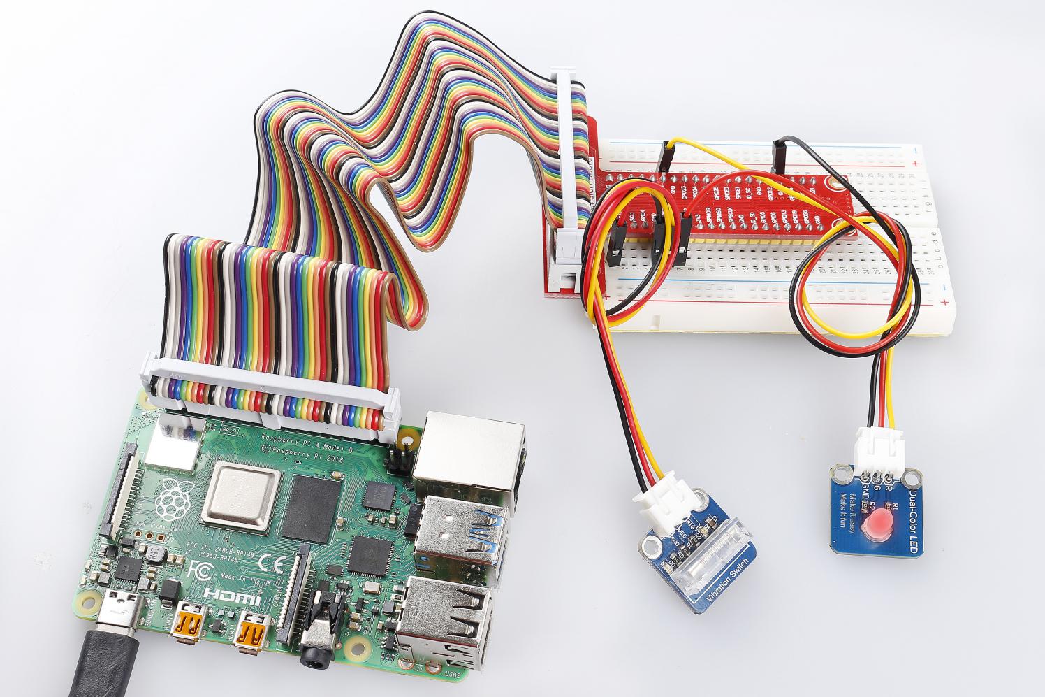
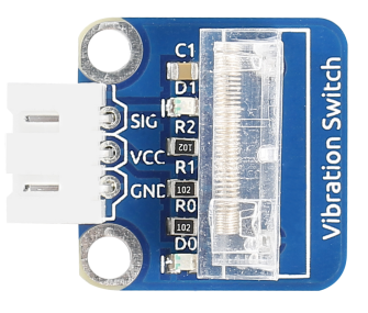
A vibration switch, also called spring switch or shock sensor, is an electronic switch which induces shock force and transfers the result to a circuit device thus triggering it to work. It contains the following parts: conductive vibration spring, switch body, trigger pin, and packaging agent.
Required Components
1 * Raspberry Pi
1 * Breadboard
1 * Dual-color LED module
1 * Vibration switch module
2 * 3-Pin anti-reverse cable
Experimental Principle
In a vibration switch module, the conductive vibration spring and trigger pin are precisely placed in the switch and fixed by adhesive. Normally, the spring and the trigger pin are separated. Once the sensor detects shock, the spring will vibrate and contact with the trigger pin, thus conducting and generating trigger signals.
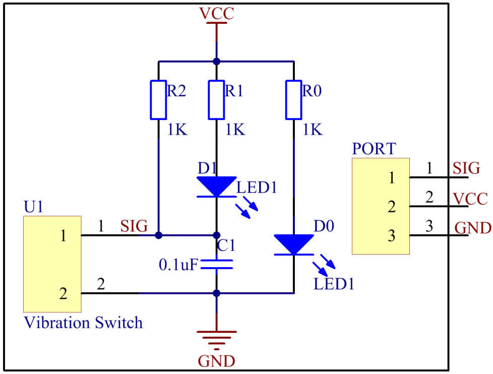
In this experiment, connect a dual-color LED module to the Raspberry Pi to indicate the changes. When you knock or tap the vibration sensor, it will get turned on and the dual-color LED will flash red. Tap it again and the LED will change to green – just between the two colors for each tap or knock. The schematic diagram:
Experimental Procedures
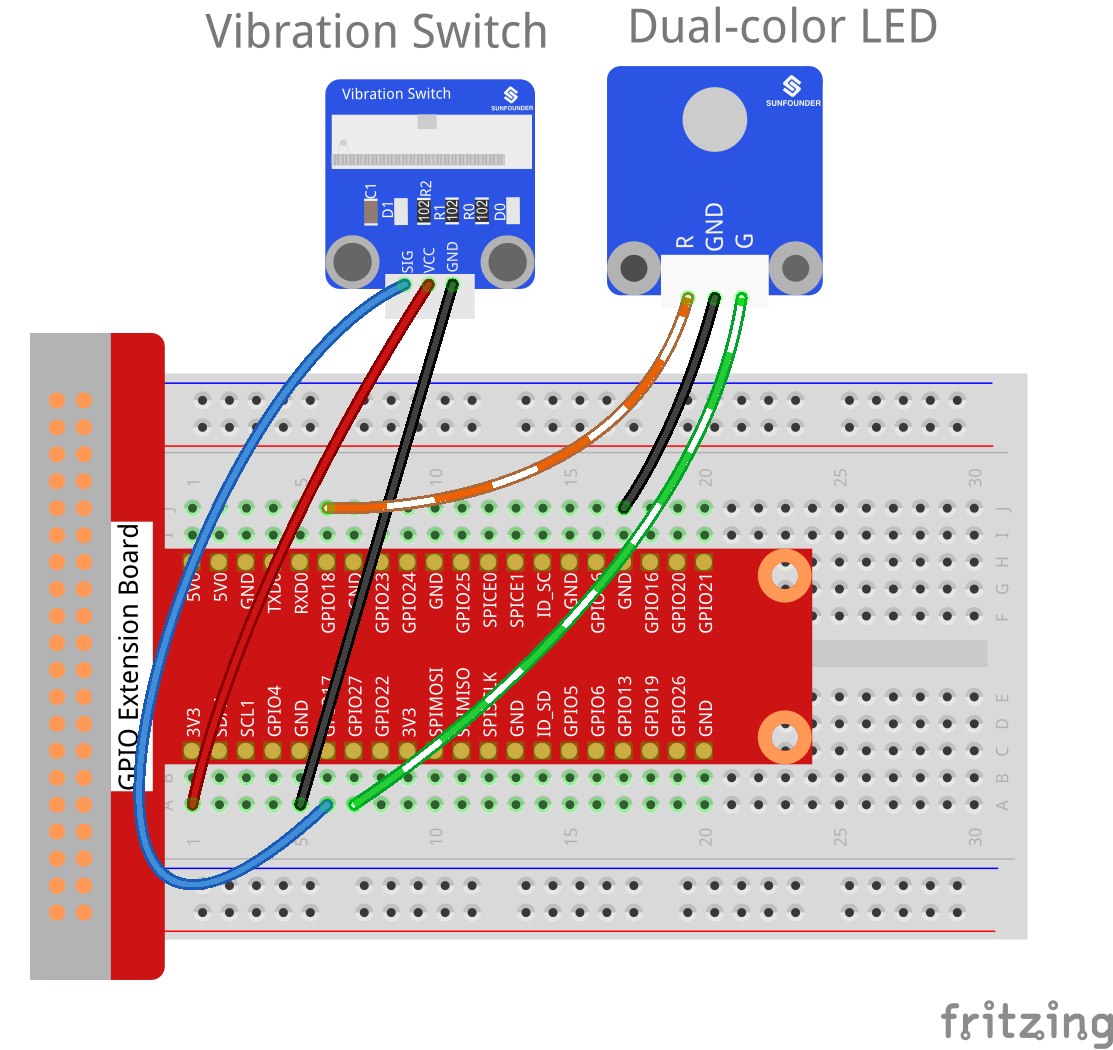
Step 1: Build the circuit.
Raspberry Pi |
GPIO Extension Board |
Vibration Switch Module |
GPIO0 |
GPIO17 |
SIG |
3.3V |
3V3 |
VCC |
GND |
GND |
GND |
Raspberry Pi |
GPIO Extension Board |
Dual-Color LED Module |
GPIO1 |
GPIO18 |
R |
GND |
GND |
GND |
GPIO2 |
GPIO27 |
G |
For C Users:
Step 2: Change directory.
cd /home/pi/SunFounder_SensorKit_for_RPi2/C/08_vibration_switch/
Step 3: Compile.
gcc vibration_switch.c -lwiringPi
Note
If it does not work after running, or there is an error prompt wiringPi.h: No such file or directory, please refer to WiringPi to install it.
Step 4: Run.
sudo ./a.out
Code
#include <wiringPi.h>
#include <stdio.h>

#define VibratePin  0
#define Gpin                2
#define Rpin                1

void LED(int color)
{
    pinMode(Gpin, OUTPUT);
    pinMode(Rpin, OUTPUT);
    if (color == 0)
    {
        digitalWrite(Rpin, HIGH);
        digitalWrite(Gpin, LOW);
    }
    else if (color == 1)
    {
        digitalWrite(Rpin, LOW);
        digitalWrite(Gpin, HIGH);
    }
    else
        printf("LED Error");
}

int main(void)
{
    int status = 0;
    int tmp = 1;
    int value = 1;
    if(wiringPiSetup() == -1){ //when initialize wiring failed,print messageto screen
        printf("setup wiringPi failed !");
        return 1;
    }

    pinMode(VibratePin, INPUT);

    while(1){
        value = digitalRead(VibratePin);
        if (tmp != value){
            status ++;
            if (status > 1){
                status = 0;
            }
            LED(status);
            delay(1000);
        }
    }
    return 0;
}
For Python Users:
Step 2: Change directory.
cd /home/pi/SunFounder_SensorKit_for_RPi2/Python/
Step 3: Run.
sudo python3 08_vibration_switch.py
Code
#!/usr/bin/env python3
import RPi.GPIO as GPIO
import time

VibratePin = 11
Gpin   = 13
Rpin   = 12

tmp = 0

def setup():
    GPIO.setmode(GPIO.BOARD)       # Numbers GPIOs by physical location
    GPIO.setup(Gpin, GPIO.OUT)     # Set Green Led Pin mode to output
    GPIO.setup(Rpin, GPIO.OUT)     # Set Red Led Pin mode to output
    GPIO.setup(VibratePin, GPIO.IN, pull_up_down=GPIO.PUD_UP)    # Set BtnPin's mode is input, and pull up to high level(3.3V)

def Led(x):
    if x == 0:
        GPIO.output(Rpin, 1)
        GPIO.output(Gpin, 0)
    if x == 1:
        GPIO.output(Rpin, 0)
        GPIO.output(Gpin, 1)

def loop():
    state = 0
    while True:
        if GPIO.input(VibratePin)==0:
            state = state + 1
            if state > 1:
                state = 0
            Led(state)
            time.sleep(1)

def destroy():
    GPIO.output(Gpin, GPIO.HIGH)       # Green led off
    GPIO.output(Rpin, GPIO.HIGH)       # Red led off
    GPIO.cleanup()                     # Release resource

if __name__ == '__main__':     # Program start from here
    setup()
    try:
        loop()
    except KeyboardInterrupt:  # When 'Ctrl+C' is pressed, the child program destroy() will be  executed.
        destroy()
Now tap or knock the module and you can see the dual-color LED flash red. Tap the sensor again, and the LED will change to green. Each tap or knock would make it change between red and green.