Lesson 4 Relay Module
Introduction
Relay is a device which is used to provide connection between two or more points or devices in response to the input signal applied. It is suitable for driving high power electric equipment, such as light bulbs, electric fans and air conditioning. You can use a relay to control high voltage with low voltage by connecting it to Raspberry Pi.
Required Components
1 * Raspberry Pi
1 * Breadboard
Several Jumper wires
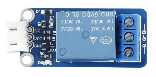
1 * Relay module
1 * Dual-color LED module
2 * 3-Pin anti-reverse cable
Experimental Principle
Relay
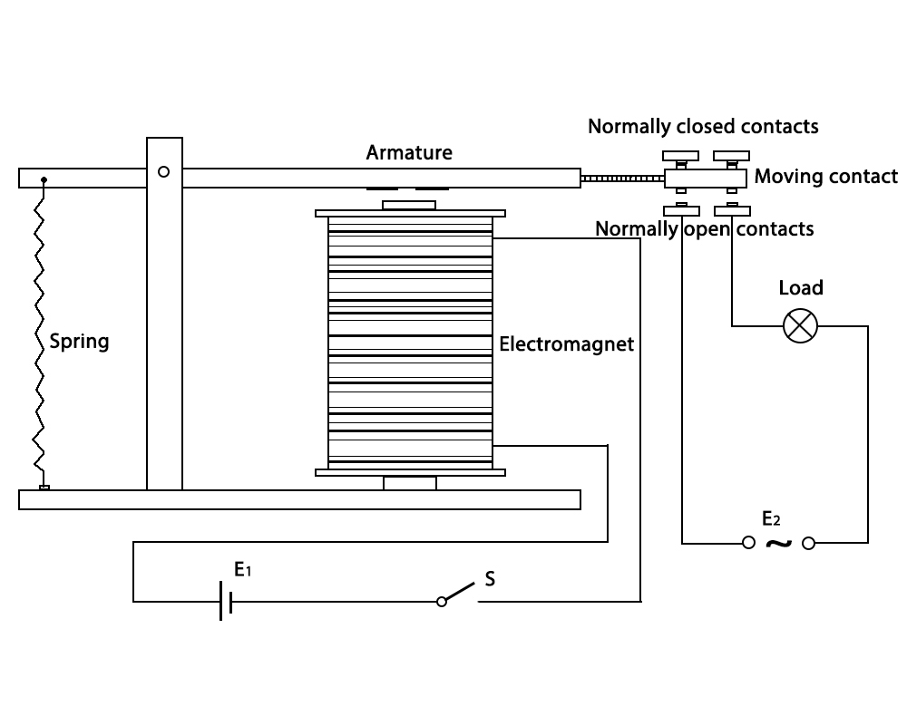
– There are 5 parts in every relay:
1. Electromagnet – It consists of an iron core wounded by coil of wires. When electricity is passed through, it becomes magnetic. Therefore, it is called electromagnet.
2. Armature – The movable magnetic strip is known as armature. When current flows through them, the coil is it energized thus producing a magnetic field which is used to make or break the normally open (N/O) or normally close (N/C) points. And the armature can be moved with direct current (DC) as well as alternating current (AC).
3. Spring – When no currents flow through the coil on the electromagnet, the spring pulls the armature away so the circuit cannot be completed.
Set of electrical contacts – There are two contact points:
Normally open - connected when the relay is activated, and disconnected when it is inactive.
Normally close – not connected when the relay is activated, and connected when it is inactive.
Molded frame – Relays are covered with plastic for protection.
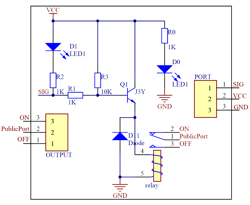
Connect the SIG pin of this module to GPIO pin. When we make GPIO pin output high level (3.3V) by programming, the transistor will conduct because of current saturation. The normally open contact of the relay will be closed, while the normally closed contact of the relay will be broken; when we make it output low level (0V), the transistor will be cut off, and the relay will recover to initial state.
The schematic diagram of the module is as shown below:
Experimental Procedures
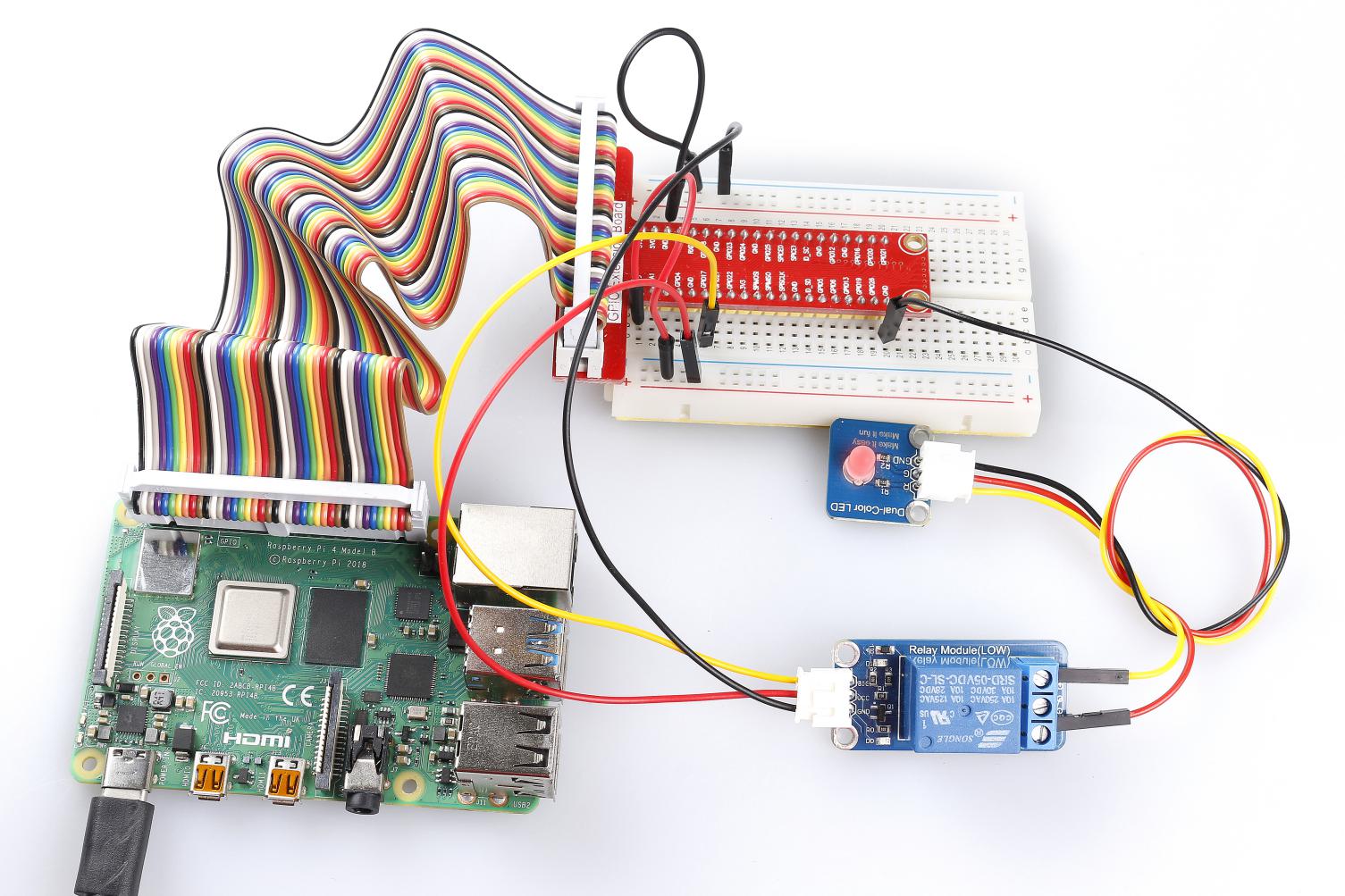
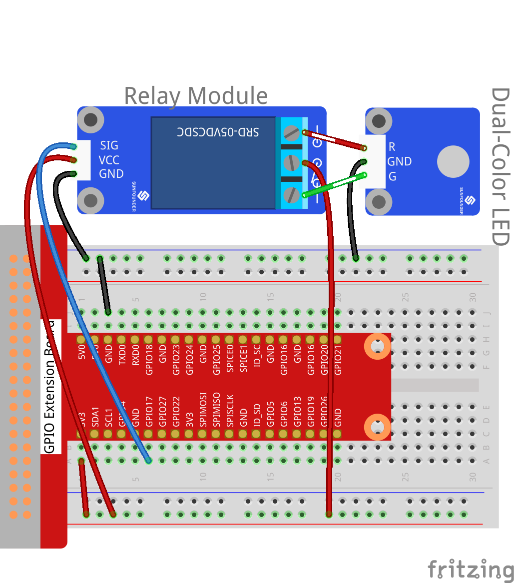
Step 1: Build the circuit.
Raspberry Pi |
GPIO Extension Board |
Relay Module |
GPIO0 |
GPIO17 |
SIG |
3.3V |
3V3 |
VCC |
GND |
GND |
GND |
3.3V |
3V3 |
COM |
Dual-color LED Module |
GPIO Extension Board |
Relay Module |
R |
* |
Normal Open |
GND |
GND |
* |
G |
* |
Normal Close |
For C Users:
Step 2: Change directory.
cd /home/pi/SunFounder_SensorKit_for_RPi2/C/04_relay/
Step 3: Compile.
gcc relay.c -lwiringPi
Note
If it does not work after running, or there is an error prompt wiringPi.h: No such file or directory, please refer to WiringPi to install it.
Step 4: Run.
sudo ./a.out
Code
#include <wiringPi.h>
#include <stdio.h>

#define RelayPin      0

int main(void)
{
   if(wiringPiSetup() == -1){ //when initialize wiring failed,print messageto screen
      printf("setup wiringPi failed !");
      return 1;
   }
//   printf("linker LedPin : GPIO %d(wiringPi pin)\n",VoicePin); //when initialize wiring successfully,print message to screen

   pinMode(RelayPin, OUTPUT);

   while(1){
         digitalWrite(RelayPin, LOW);
         delay(1000);
         digitalWrite(RelayPin, HIGH);
         delay(1000);
   }

   return 0;
}
For Python Users:
Step 2: Change directory.
cd /home/pi/SunFounder_SensorKit_for_RPi2/Python/
Step 3: Run.
sudo python3 04_relay.py
Code
#!/usr/bin/env python3
import RPi.GPIO as GPIO
import time

RelayPin = 11    # pin11

def setup():
   GPIO.setmode(GPIO.BOARD)       # Numbers GPIOs by physical location
   GPIO.setup(RelayPin, GPIO.OUT)
   GPIO.output(RelayPin, GPIO.HIGH)

def loop():
   while True:
      #'...relayd on'
      GPIO.output(RelayPin, GPIO.LOW)
      time.sleep(0.5)
      #'relay off...'
      GPIO.output(RelayPin, GPIO.HIGH)
      time.sleep(0.5)

def destroy():
   GPIO.output(RelayPin, GPIO.HIGH)
   GPIO.cleanup()                     # Release resource

if __name__ == '__main__':     # Program start from here
   setup()
   try:
      loop()
   except KeyboardInterrupt:  # When 'Ctrl+C' is pressed, the child program destroy() will be  executed.
      destroy()
Now, you may hear the ticktock. That’s the normally closed contact opened and the normally open contact closed. You can attach a high voltage device you want to control, like a 220V bulb, to the output port of the relay. Then the relay will act as an automatic switch.