Lesson 11 Reed Switch
Introduction
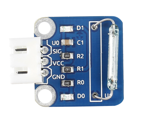
A reed switch (as shown below) is used to detect the magnetic field. Hall sensors are generally used to measure the speed of intelligent vehicles and count in assembly lines, while reed switches are often used to detect the existence of a magnetic field.
Required Components
1 * Raspberry Pi
1 * Breadboard
1 * Reed switch module
1 * Dual-color LED module
2 * 3-Pin anti-reverse cable
1 * Magnet (Self provided)
Experimental Principle
A reed switch is a type of line switch component that realizes control by magnetic signals. It induces by a magnet. The “switch” here means dry reed pipe, which is a kind of contact passive electronic switch component with the advantage of simple structure, small size, and convenient control. The shell of a reed switch is commonly a sealed glass pipe in which two iron elastic reed electroplates are equipped and inert gases are filled. Normally, the two reeds made of special materials in the glass tube are separated. However, when a magnetic substance approaches the glass tube, the two reeds in the glass tube are magnetized to attract each other and contact under the function of magnetic field lines. As a result, the two reeds will pull together to connect the circuit connected with the nodes.
After external magnetic force disappears, the two reeds will be separated with each other because they have the same magnetism, so the circuit is also disconnected. Therefore, as a line switch component controlling by magnetic signals, the dry reed pipe can be used as a sensor to count, limit positions and so on. At the same time, it is widely used in a variety of communication devices.
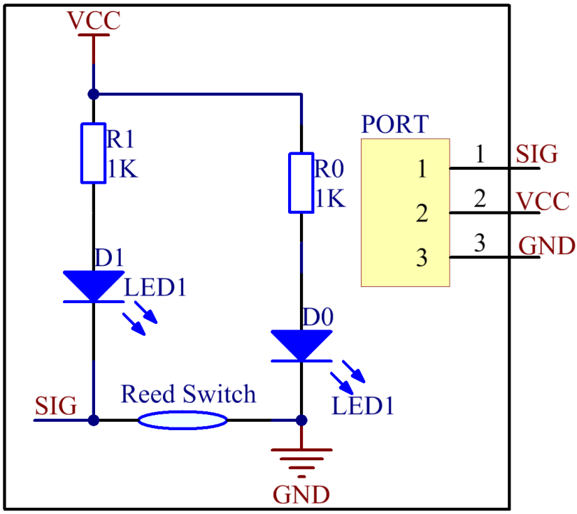
The schematic diagram of the module is as shown below:
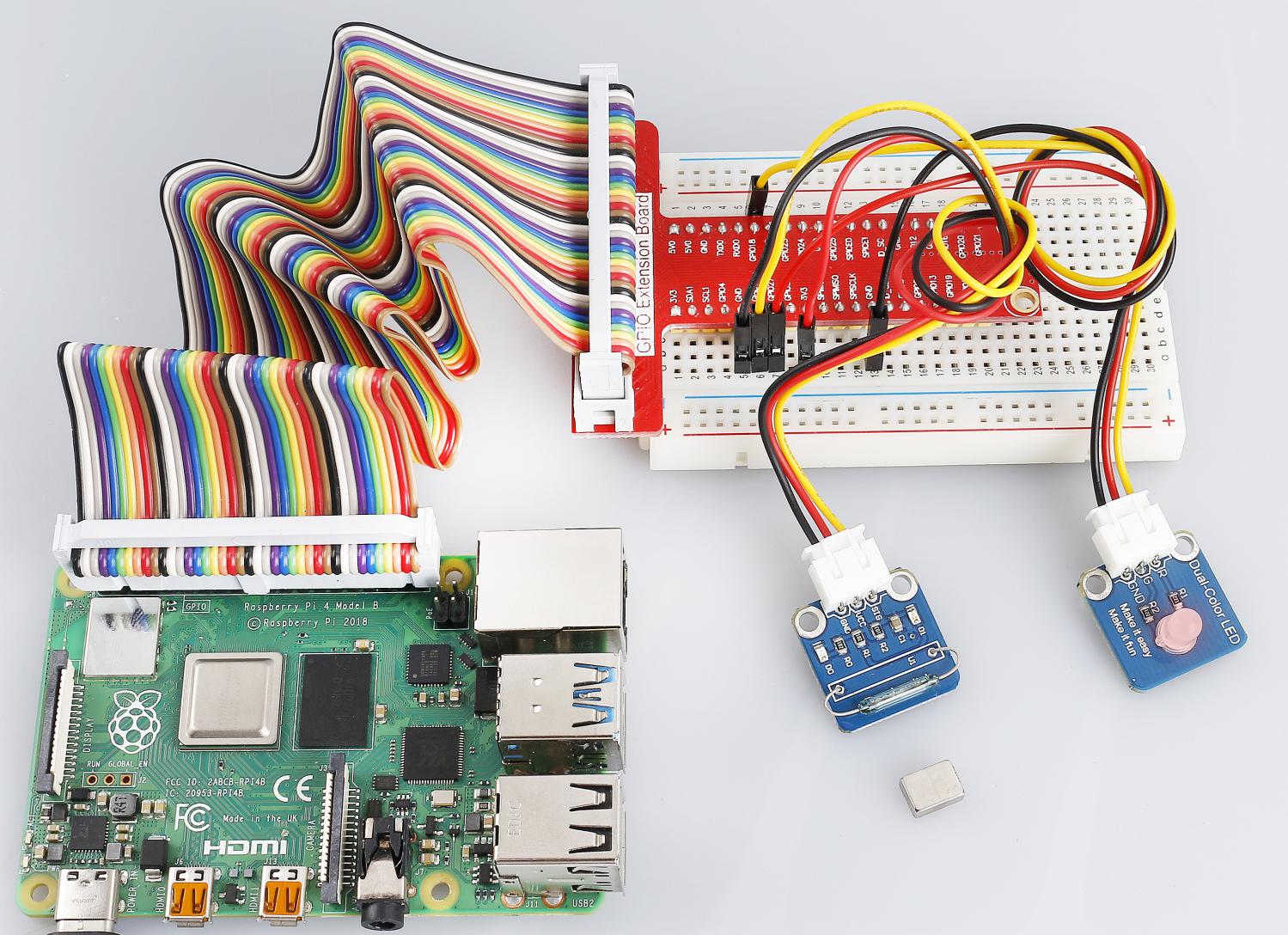
Experimental Procedures
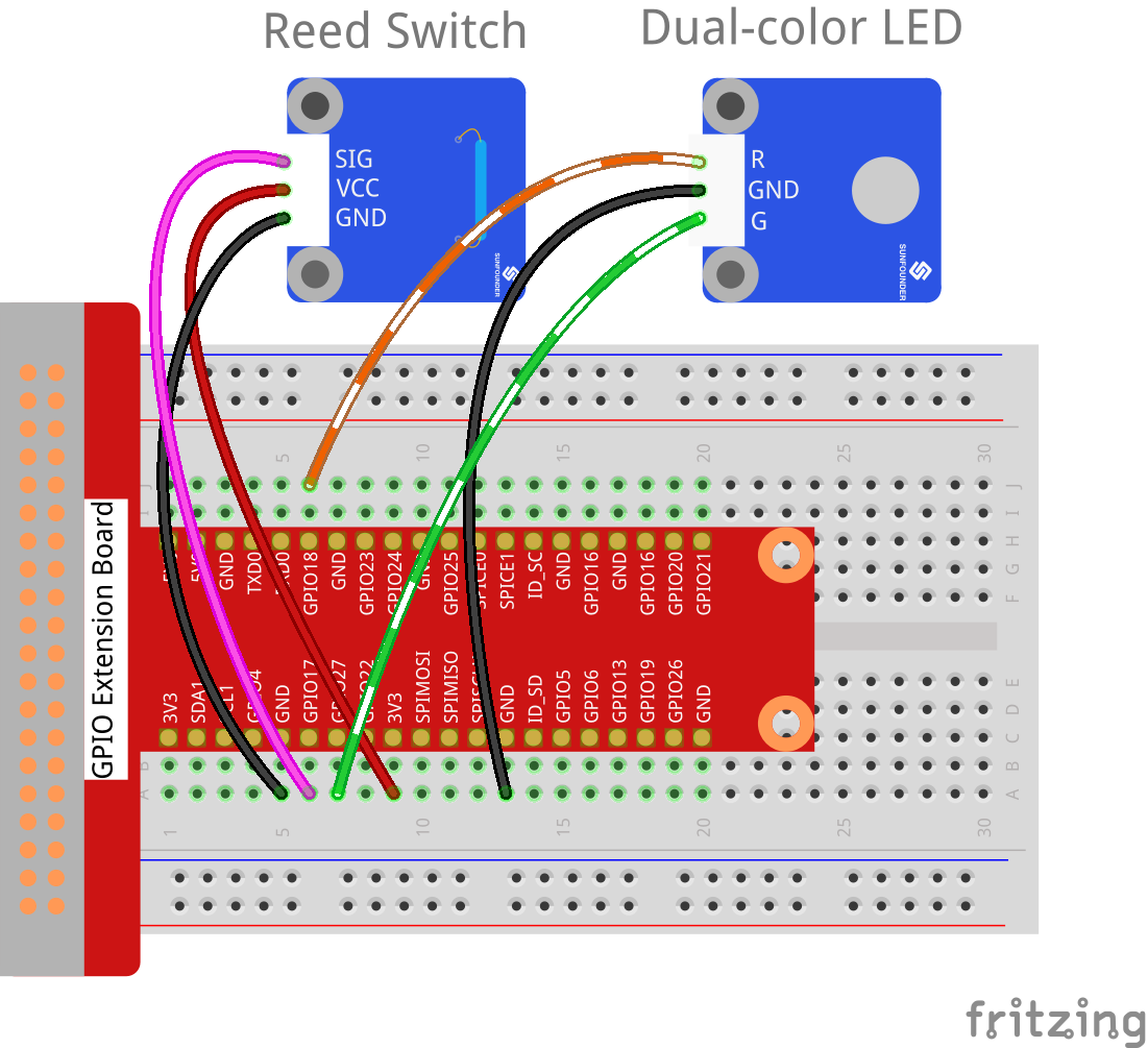
Step 1: Build the circuit
Raspberry Pi |
GPIO Extension Board |
Reed Switch Module |
GPIO0 |
GPIO17 |
SIG |
3.3V |
3V3 |
VCC |
GND |
GND |
GND |
Raspberry Pi |
GPIO Extension Board |
Dual-color LED Module |
GPIO1 |
GPIO18 |
R |
GND |
GND |
GND |
GPIO2 |
GPIO27 |
G |
For C Users:
Step 2: Change directory.
cd /home/pi/SunFounder_SensorKit_for_RPi2/C/11_reed_switch/
Step 3: Compile.
gcc reed_switch.c -lwiringPi
Note
If it does not work after running, or there is an error prompt wiringPi.h: No such file or directory, please refer to WiringPi to install it.
Step 4: Run.
sudo ./a.out
Code
#include <wiringPi.h>
#include <stdio.h>

#define ReedPin             0
#define Gpin                2
#define Rpin                1

void LED(char* color)
{
    pinMode(Gpin, OUTPUT);
    pinMode(Rpin, OUTPUT);
    if (color == "RED")
    {
        digitalWrite(Rpin, HIGH);
        digitalWrite(Gpin, LOW);
    }
    else if (color == "GREEN")
    {
        digitalWrite(Rpin, LOW);
        digitalWrite(Gpin, HIGH);
    }
    else
        printf("LED Error");
}

int main(void)
{
    if(wiringPiSetup() == -1){ //when initialize wiring failed,print messageto screen
        printf("setup wiringPi failed !");
        return 1;
    }

    pinMode(ReedPin, INPUT);
    LED("GREEN");

    while(1){
        if(0 == digitalRead(ReedPin)){
            delay(10);
            if(0 == digitalRead(ReedPin)){
                LED("RED");
                printf("Detected Magnetic Material!\n");
            }
        }
        else if(1 == digitalRead(ReedPin)){
            delay(10);
            if(1 == digitalRead(ReedPin)){
                while(!digitalRead(ReedPin));
                LED("GREEN");
            }
        }
    }
    return 0;
}
For Python Users:
Step 2: Change directory.
cd /home/pi/SunFounder_SensorKit_for_RPi2/Python/
Step 3: Run.
sudo python3 11_reed_switch.py
Code
#!/usr/bin/env python3
import RPi.GPIO as GPIO

ReedPin = 11
Gpin    = 13
Rpin    = 12

def setup():
    GPIO.setmode(GPIO.BOARD)       # Numbers GPIOs by physical location
    GPIO.setup(Gpin, GPIO.OUT)     # Set Green Led Pin mode to output
    GPIO.setup(Rpin, GPIO.OUT)     # Set Red Led Pin mode to output
    GPIO.setup(ReedPin, GPIO.IN, pull_up_down=GPIO.PUD_UP)    # Set BtnPin's mode is input, and pull up to high level(3.3V)
    GPIO.add_event_detect(ReedPin, GPIO.BOTH, callback=detect, bouncetime=200)

def Led(x):
    if x == 0:
        GPIO.output(Rpin, 1)
        GPIO.output(Gpin, 0)
    if x == 1:
        GPIO.output(Rpin, 0)
        GPIO.output(Gpin, 1)

def detect(chn):
    Led(GPIO.input(ReedPin))

def loop():
    while True:
        pass

def destroy():
    GPIO.output(Gpin, GPIO.HIGH)       # Green led off
    GPIO.output(Rpin, GPIO.HIGH)       # Red led off
    GPIO.cleanup()                     # Release resource

if __name__ == '__main__':     # Program start from here
    setup()
    try:
        loop()
    except KeyboardInterrupt:  # When 'Ctrl+C' is pressed, the child program destroy() will be  executed.
        destroy()
Then the LED will flash green. Place a magnet near the reed switch, “Detected Magnetic Material!” will be printed on the screen and the LED will change to red. Move away the magnet, the LED will turn green again.