Lesson 16 Potentiometer Module
Introduction
A potentiometer is a device which is used to vary the resistance in an electrical circuit without interrupting the circuit.
Required Components
1 * Raspberry Pi
1 * Breadboard
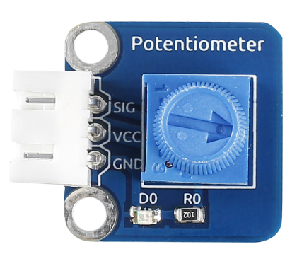
1 * Potentiometer module
1 * Dual-Color LED module
2 * 3-Pin anti-reverse cable
Several Jumper wires
Experimental Principle
An analog potentiometer is an analog electronic component. What’s the difference between an analog one and a digital one? Simply put, a digital potentiometer refers to just two states like on/off, high/low levels, i.e. either 0 or 1, while a digital one supports analog signals like a number from 1 to 1000. The signal value changes over time instead of keeping an exact number. Analog signals include light intensity, humidity, temperature, and so on.
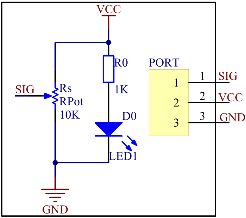
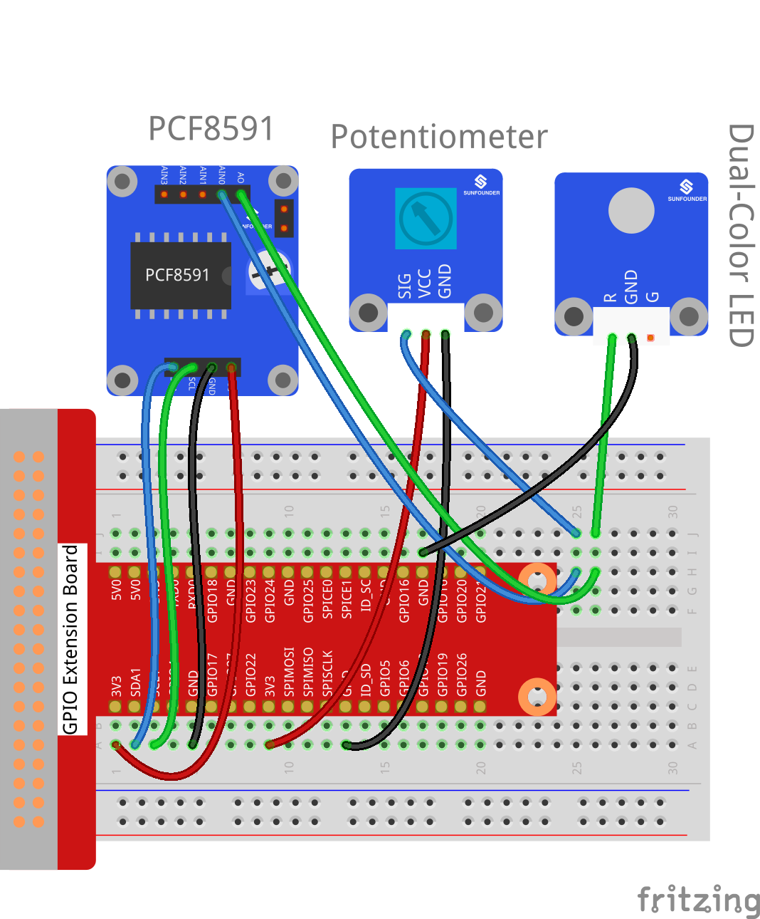
In this experiment, PCF8591 is used to read the analog value of the potentiometer and output the value to LED. Connect pin SIG of the potentiometer to pin AIN0 of PCF8591. Connect pin R or Pin G of the Dual-Color LED to pin AOUT of PCF8591 to observe the change of LED.
The schematic diagram of the module is as shown below:
Experimental Procedures
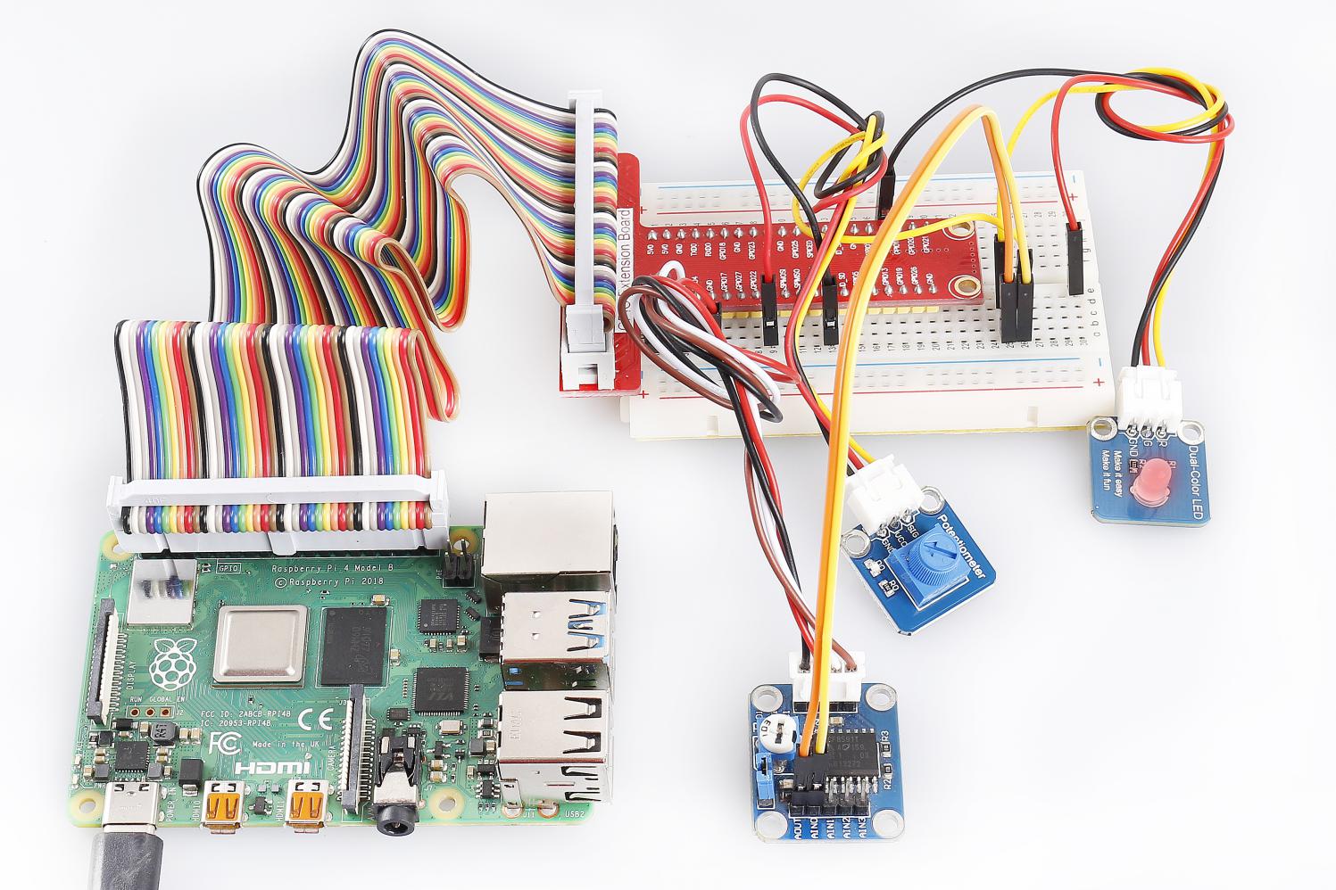
Step 1: Build the circuit.
Raspberry Pi |
GPIO Extension Board |
PCF8591 Module |
SDA |
SDA1 |
SDA |
SCL |
SCL1 |
SCL |
3.3V |
3V3 |
VCC |
GND |
GND |
GND |
Potentiometer |
GPIO Extension Board |
PCF8591 Module |
SIG |
* |
AIN0 |
VCC |
3V3 |
VCC |
GND |
GND |
GND |
Dual-Color Module |
GPIO Extension Board |
PCF8591 Module |
R |
* |
AOUT |
GND |
GND |
GND |
G |
* |
* |
For C Users:
Step 2: Change directory.
cd /home/pi/SunFounder_SensorKit_for_RPi2/C/16_potentiometer/
Step 3: Compile.
gcc potentiometer.c -lwiringPi
Note
If it does not work after running, or there is an error prompt wiringPi.h: No such file or directory, please refer to WiringPi to install it.
Step 4: Run.
sudo ./a.out
Code
#include <stdio.h>
#include <wiringPi.h>
#include <pcf8591.h>

#define PCF       120

int main (void)
{
    int value ;
    wiringPiSetup () ;
    // Setup pcf8591 on base pin 120, and address 0x48
    pcf8591Setup (PCF, 0x48) ;
    while(1) // loop forever
    {
        value = analogRead  (PCF + 0) ;
        printf("Value: %d\n", value);
        analogWrite (PCF + 0, value) ;
        delay (200) ;
    }
    return 0 ;
}
For Python Users:
Step 2: Change directory.
cd /home/pi/SunFounder_SensorKit_for_RPi2/Python/
Step 3: Run.
sudo python3 16_potentiometer.py
Code
#!/usr/bin/env python3
import PCF8591 as ADC
import time

def setup():
    ADC.setup(0x48)

def loop():
    status = 1
    while True:
        print ('Value:', ADC.read(0))
        Value = ADC.read(0)
        outvalue = map(Value,0,255,120,255)
        ADC.write(outvalue)
        time.sleep(0.2)
def destroy():
    ADC.write(0)

def map(x, in_min, in_max, out_min, out_max):
        '''To map the value from arange to another'''
        return (x - in_min) * (out_max - out_min) / (in_max - in_min) + out_min

if __name__ == '__main__':
    try:
        setup()
        loop()
    except KeyboardInterrupt:
        destroy()
Turn the knob of the potentiometer, and you can see the value printed on the screen change from 0 (minimum) to 255 (maximum).