Lesson 26 DS18B20 Temperature Sensor
Introduction
Temperature Sensor DS18B20 is a commonly used digital temperature sensor featured with small size, low-cost hardware, strong anti-interference capability and high precision. The digital temperature sensor is easy to wire and can be applied a various occasions after packaging. Different from conventional AD collection temperature sensors, it uses a 1-wire bus and can directly output temperature data.
Required Components
1 * Raspberry Pi
1 * Breadboard
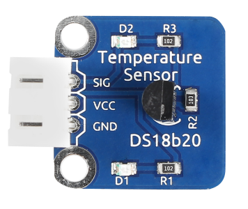
1 * DS18B20 Temperature Sensor module
1 * 3-Pin anti-reverse cable
Experimental Principle
With a unique single-wire interface, DS18B20 requires only one pin for a two-way communication with a microprocessor. It supports multi-point networking to measure multi-point temperatures. Eight sensors can be connected at most, because it will consume too much power supply and cause low voltage thus harming the stability of transmission.
When using the DS18B20, you need to connect a 10KΩ resistor to the middle pin DQ to pull up the level. The schematic diagram of the module is as shown below:

Experimental Procedures
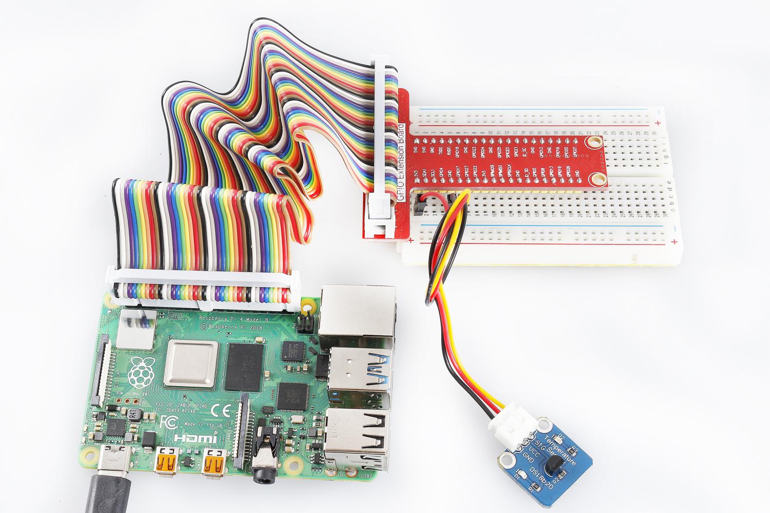
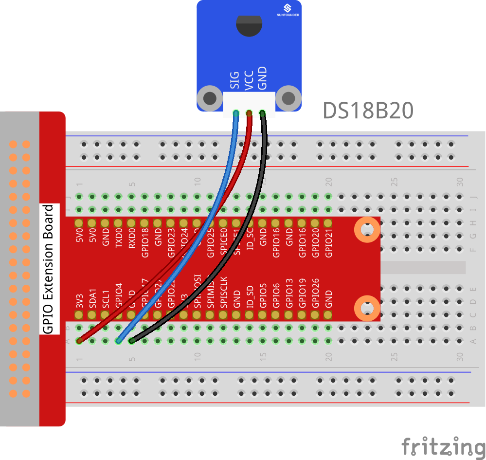
Step 1: Build the circuit according to the following method.
Raspberry Pi |
GPIO Extension Board |
DS18B20 Temperature Sensor |
GPIO7 |
GPIO4 |
SIG |
3.3V |
3V3 |
VCC |
GND |
GND |
GND |
Step 2: Upgrade your kernel.
sudo apt-get update
sudo apt-get upgrade
Step 3: You can edit that file with nano.
sudo nano /boot/config.txt
Then scroll to the bottom and type.
dtoverlay = w1-gpio
Then reboot with
sudo reboot
Mount the device drivers and confirm whether the device is effective or not.
sudo modprobe w1-gpio
sudo modprobe w1-therm
cd /sys/bus/w1/devices/
ls
The result is as follows:
root@rasberrypi:/sys/bus/w1/devices# ls
28-00000495db35 w1_bus_master1
28-00000495db35 is an external temperature sensor device, but it may vary with every client. This is the serial number of your ds18b20.
Step 4: Check the current temperature.
cd 28-00000495db35
ls
The result is as follows:
root@rasberrypi:/sys/bus/w1/devices/28-00000495db35# ls
driver  id  name  power  subsystem  uevent  w1_slave
cat w1_slave
The result is as follows:
root@raspberrypi:/sys/bus/w1_slave/28-00000495db35# cat w1_slave
a3 01 4b 46 7f ff 0d 10 ce : crc=ce YES
a3 01 4b 46 7f ff 0d 10 ce t=26187
The second line t=26187 is current temperature value. If you want to convert it to degree Celsius, you can divide by 1000, that is, the current temperature is 26187/1000=26.187 ℃.
For C Users:
Step 2: Change directory and edit.
cd /home/pi/SunFounder_SensorKit_for_RPi2/C/26_ds18b20/
Open the ds18b20.c to change the sensor address.
nano ds18b20.c
Find the following line, replace “28-00000495db35” with your sensor address. Save and exit.
fd = open("/sys/bus/w1/devices/28-031590bf4aff/w1_slave", O_RDONLY);
Step 6: Compile.
gcc ds18b20.c -lwiringPi
Note
If it does not work after running, or there is an error prompt wiringPi.h: No such file or directory, please refer to WiringPi to install it.
Step 7: Run.
sudo ./a.out
Code
#include <wiringPi.h>
#include <sys/types.h>
#include <sys/stat.h>
#include <fcntl.h>
#include <unistd.h>
#include <errno.h>
#include <stdlib.h>
#include <stdio.h>

#define             BUFSIZE         128

typedef unsigned char uchar;
typedef unsigned int  uint;

float tempRead(void)
{
    float temp;
    int i, j;
    int fd;
    int ret;

    char buf[BUFSIZE];
    char tempBuf[5];

    fd = open("/sys/bus/w1/devices/28-031590bf4aff/w1_slave", O_RDONLY);

    if(-1 == fd){
        perror("open device file error");
        return 1;
    }

    while(1){
        ret = read(fd, buf, BUFSIZE);
        if(0 == ret){
            break;
        }
        if(-1 == ret){
            if(errno == EINTR){
                continue;
            }
            perror("read()");
            close(fd);
            return 1;
        }
    }

    for(i=0;i<sizeof(buf);i++){
        if(buf[i] == 't'){
            for(j=0;j<sizeof(tempBuf);j++){
                tempBuf[j] = buf[i+2+j];
            }
        }
    }

    temp = (float)atoi(tempBuf) / 1000;

    close(fd);

    return temp;
}

int main(void)
{
    if(wiringPiSetup() == -1){
        printf("setup wiringPi failed !");
        return 1;
    }
    float temp;
    while(1){
        temp = tempRead();
        printf("Current temperature : %0.3f\n", temp);
    }
    return 0;
}
For Python Users:
Step 5: Change directory and edit.
cd /home/pi/SunFounder_SensorKit_for_RPi2/Python/
nano 26_ds18b20.py
Find the following code, replace 28-031590bf4aff with your sensor address.
def setup():
    global ds18b20
    for i in os.listdir('/sys/bus/w1/devices'):
        if i != 'w1_bus_master1':
            ds18b20 = '28-031590bf4aff'
Press Ctrl + X -> Y -> Enter to save and exit.
Step 6: Run.
sudo python3 26_ds18b20.py
Code
#!/usr/bin/env python3
import os

ds18b20 = ''

def setup():
    global ds18b20
    for i in os.listdir('/sys/bus/w1/devices'):
        if i != 'w1_bus_master1':
            ds18b20 = '28-031590bf4aff'

def read():
#   global ds18b20
    location = '/sys/bus/w1/devices/' + ds18b20 + '/w1_slave'
    tfile = open(location)
    text = tfile.read()
    tfile.close()
    secondline = text.split("\n")[1]
    temperaturedata = secondline.split(" ")[9]
    temperature = float(temperaturedata[2:])
    temperature = temperature / 1000
    return temperature

def loop():
    while True:
        if read() != None:
            print ("Current temperature : %0.3f C" % read())

def destroy():
    pass

if __name__ == '__main__':
    try:
        setup()
        loop()
    except KeyboardInterrupt:
        destroy()
Now, you can see the current temperature value displayed on the screen.