Lesson 27 Rotary Encoder Module
Introduction
A rotary encoder is an electro-mechanical device that converts the angular position or motion of a shaft or axle to analog or digital code. Rotary encoders are usually placed at the side which is perpendicular to the shaft. They act as sensors for detecting angle, speed, length, position, and acceleration in automation field.
Required Components
1 * Raspberry Pi
1 * Breadboard
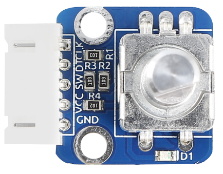
1 * Rotary Encoder module
1 * 5-Pin anti-reverse cable
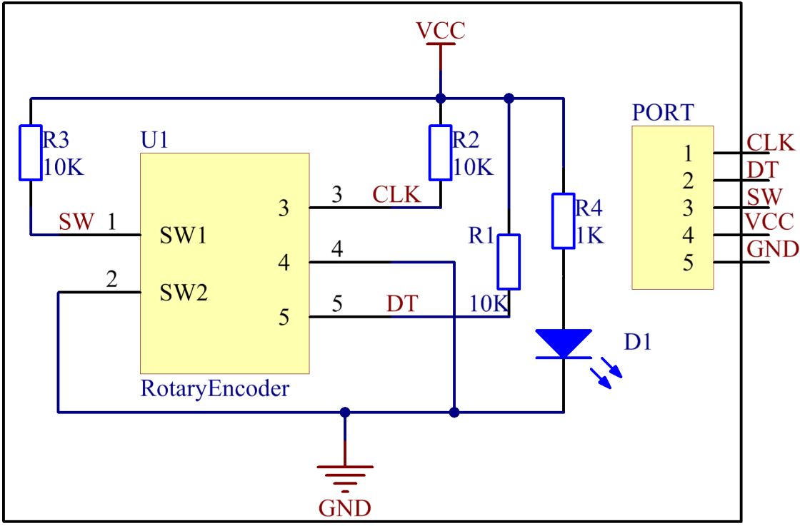
Experimental Principle
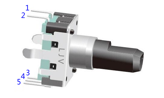
Most rotary encoders have 5 pins with three functions of turning left & right and pressing down. Pin 1 and pin 2 are switch wiring terminals used to press. They are similar to buttons previously mentioned, so we will no longer discuss them in this experiment. Pin 4 is generally connected to ground. Pin 3 and pin 5 are first connected to pull-up resistor and then to the microprocessor. In this experiment, they are connected to GPIO0 and GPIO1 of Raspberry Pi. When it is rotated left and right, there will be pulse inputs in pin 1 and pin 3.
It shows that if output 1 is high and output 2 is high, then the switch rotates clockwise; if output 1 is high and output 2 is low, then the switch rotates counterclockwise. As a result, during SCM programming, if output 1 is high, then you can tell whether the rotary encoder rotates left or right as long as you know the state of output 2.
Experimental Procedures
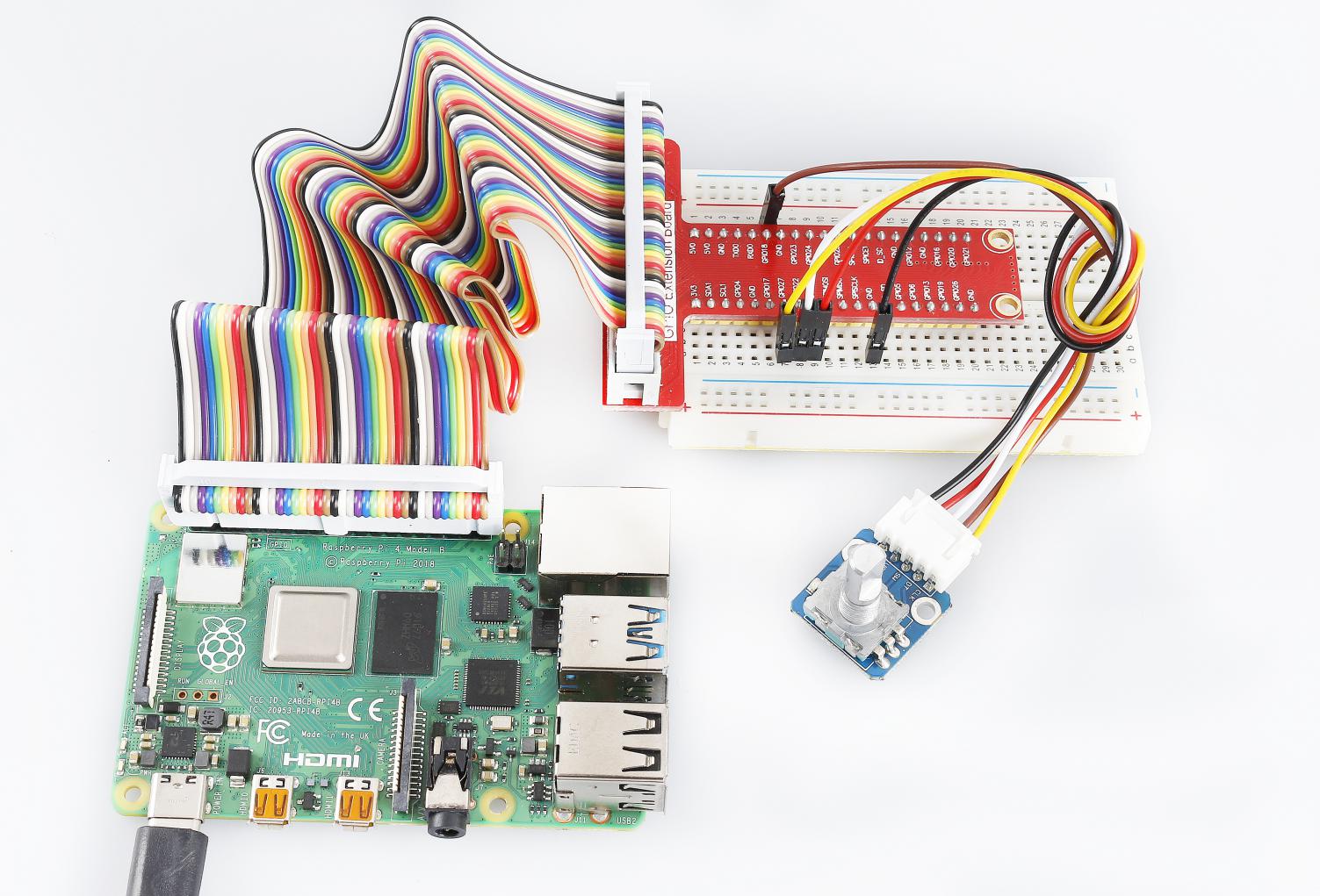
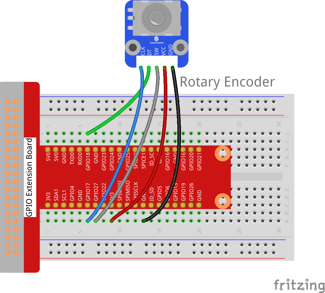
Step 1: Build the circuit.
Raspberry Pi |
GPIO Extension Board |
Rotary Encoder Module |
GPIO0 |
GPIO17 |
CLK |
GPIO1 |
GPIO18 |
DT |
GPIO2 |
GPIO27 |
SW |
3.3V |
3V3 |
VCC |
GND |
GND |
GND |
For C Users:
Step 2: Change directory.
cd /home/pi/SunFounder_SensorKit_for_RPi2/C/27_rotary_encoder/
Step 3: Compile.
gcc rotary_encoder.c -lwiringPi
Note
If it does not work after running, or there is an error prompt wiringPi.h: No such file or directory, please refer to WiringPi to install it.
Step 4: Run.
sudo ./a.out
Code
#include <stdio.h>
#include <string.h>
#include <errno.h>
#include <stdlib.h>
#include <wiringPi.h>

#define  RoAPin    0
#define  RoBPin    1
#define  SWPin     2

static volatile int globalCounter = 0 ;

unsigned char flag;
unsigned char Last_RoB_Status;
unsigned char Current_RoB_Status;

void btnISR(void)
{
    globalCounter = 0;
}

void rotaryDeal(void)
{
    Last_RoB_Status = digitalRead(RoBPin);

    while(!digitalRead(RoAPin)){
        Current_RoB_Status = digitalRead(RoBPin);
        flag = 1;
    }

    if(flag == 1){
        flag = 0;
        if((Last_RoB_Status == 0)&&(Current_RoB_Status == 1)){
            globalCounter ++;
        }
        if((Last_RoB_Status == 1)&&(Current_RoB_Status == 0)){
            globalCounter --;
        }
    }
}

int main(void)
{
    if(wiringPiSetup() < 0){
        fprintf(stderr, "Unable to setup wiringPi:%s\n",strerror(errno));
        return 1;
    }

    pinMode(SWPin, INPUT);
    pinMode(RoAPin, INPUT);
    pinMode(RoBPin, INPUT);

    pullUpDnControl(SWPin, PUD_UP);

    if(wiringPiISR(SWPin, INT_EDGE_FALLING, &btnISR) < 0){
        fprintf(stderr, "Unable to init ISR\n",strerror(errno));
        return 1;
    }

    int tmp = 0;

    while(1){
        rotaryDeal();
        if (tmp != globalCounter){
            printf("%d\n", globalCounter);
            tmp = globalCounter;
        }
    }

    return 0;
}
For Python Users:
Step 2: Change directory.
cd /home/pi/SunFounder_SensorKit_for_RPi2/Python/
Step 3: Run.
sudo python3 27_rotary_encoder.py
Code
#!/usr/bin/env python3
import RPi.GPIO as GPIO
import time

RoAPin = 11    # CLK Pin
RoBPin = 12    # DT Pin
BtnPin = 13    # Button Pin

globalCounter = 0

flag = 0
Last_RoB_Status = 0
Current_RoB_Status = 0

def setup():
    GPIO.setmode(GPIO.BOARD)       # Numbers GPIOs by physical location
    GPIO.setup(RoAPin, GPIO.IN)    # input mode
    GPIO.setup(RoBPin, GPIO.IN)
    GPIO.setup(BtnPin, GPIO.IN, pull_up_down=GPIO.PUD_UP)

def rotaryDeal():
    global flag
    global Last_RoB_Status
    global Current_RoB_Status
    global globalCounter
    Last_RoB_Status = GPIO.input(RoBPin)
    while(not GPIO.input(RoAPin)):
        Current_RoB_Status = GPIO.input(RoBPin)
        flag = 1
    if flag == 1:
        flag = 0
        if (Last_RoB_Status == 0) and (Current_RoB_Status == 1):
            globalCounter = globalCounter + 1
        if (Last_RoB_Status == 1) and (Current_RoB_Status == 0):
            globalCounter = globalCounter - 1

def btnISR(channel):
    global globalCounter
    globalCounter = 0

def loop():
    global globalCounter
    tmp = 0 # Rotary Temperary

    GPIO.add_event_detect(BtnPin, GPIO.FALLING, callback=btnISR)
    while True:
        rotaryDeal()
        if tmp != globalCounter:
            print ('globalCounter = %d' % globalCounter)
            tmp = globalCounter

def destroy():
    GPIO.cleanup()             # Release resource

if __name__ == '__main__':     # Program start from here
    setup()
    try:
        loop()
    except KeyboardInterrupt:  # When 'Ctrl+C' is pressed, the child program destroy() will be  executed.
        destroy()
Now rotate the shaft of the rotary encoder, and the value printed on the screen will change. Rotate the rotary encoder clockwise, the value will increase; Rotate it counterclockwise, the value will decrease; Press the rotary encoder, the value will be reset to 0.