Lesson 20 Photoresistor Module
Introduction
A photoresistor is a light-controlled variable resistor. The resistance of a photoresistor decreases with increasing incident light intensity.
Required Components
1 * Raspberry Pi
1 * Breadboard
1 * PCF8591
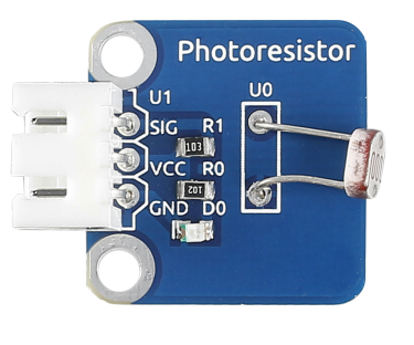
1 * Photoresistor module
1 * 3-Pin anti-reverse cable
Several Jumper wires
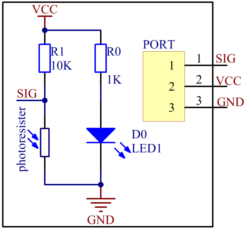
Experimental Principle
With light intensity increasing, the resistance of a photoresistor will decrease. Thus the output voltage changes. Analog signals collected by the photoresistor are converted to digital signals through PCF8591. Then these digital signals are transmitted to Raspberry Pi and printed on the screen. The schematic diagram:
Experimental Procedures
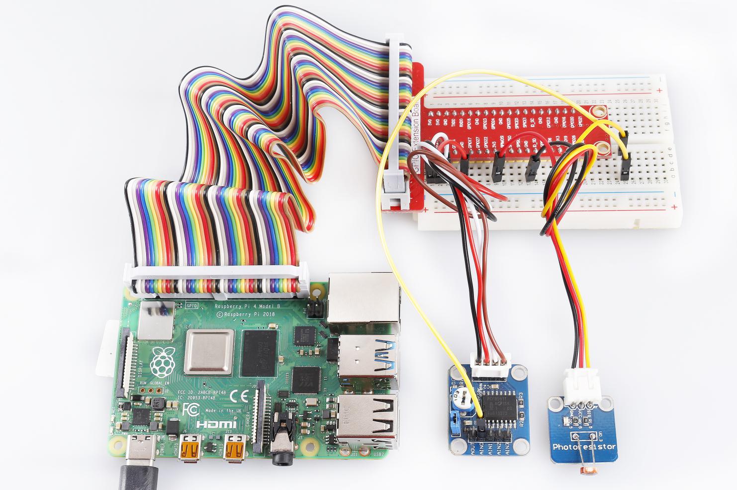
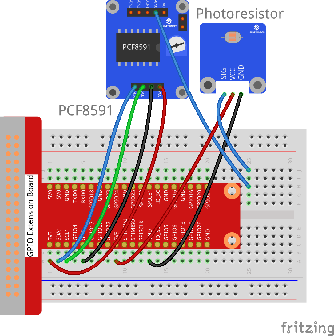
Step 1: Build the circuit.
Raspberry Pi |
GPIO Extension Board |
PCF8591 Module |
SDA |
SDA1 |
SDA |
SCL |
SCL1 |
SCL |
3.3V |
3V3 |
VCC |
GND |
GND |
GND |
Photoresistor |
GPIO Extension Board |
PCF8591 Module |
SIG |
* |
AIN0 |
VCC |
3V3 |
VCC |
GND |
GND |
GND |
For C Users:
Step 2: Change directory.
cd /home/pi/SunFounder_SensorKit_for_RPi2/C/20_photoresistor/
Step 3: Compile.
gcc photoresistor.c -lwiringPi
Note
If it does not work after running, or there is an error prompt wiringPi.h: No such file or directory, please refer to WiringPi to install it.
Step 4: Run.
sudo ./a.out
Code
#include <stdio.h>
#include <wiringPi.h>
#include <pcf8591.h>
#include <math.h>

#define             PCF     120
#define             DOpin   0

int main()
{
    int analogVal;

    if(wiringPiSetup() == -1){
        printf("setup wiringPi failed !");
        return 1;
    }
    // Setup pcf8591 on base pin 120, and address 0x48
    pcf8591Setup(PCF, 0x48);

    while(1) // loop forever
    {
        analogVal = analogRead(PCF + 0);
        printf("Value: %d\n", analogVal);

        delay (200);
    }
    return 0;
}
For Python Users:
Step 2: Change directory.
cd /home/pi/SunFounder_SensorKit_for_RPi2/Python/
Step 3: Run.
sudo python3 20_photoresistor.py
Code
#!/usr/bin/env python3
import PCF8591 as ADC
import RPi.GPIO as GPIO
import time

DO = 17
GPIO.setmode(GPIO.BCM)

def setup():
    ADC.setup(0x48)
    GPIO.setup(DO, GPIO.IN)


def loop():
    status = 1
    while True:
        print ('Value: ', ADC.read(0))

        time.sleep(0.2)

if __name__ == '__main__':
    try:
        setup()
        loop()
    except KeyboardInterrupt:
        pass
Now, change light intensity (e.g. cover the module with a pad), and the value printed on the screen will change accordingly.