Lesson 35 Intelligent Temperature Measurement System
Introduction
In this experiment, we will use some modules together to build an intelligent temperature measurement system.
Required Components
1 * Raspberry Pi
1 * Breadboard
1 * Active Buzzer
1 * RGB LED Module
1 * DS18B20 Temperature Sensor
1 * PCF8591
1 * Joystick PS2
Several Jumper wires
Experimental Principle
It is similar with lesson 26. The only difference is that we can adjust the lower limit and upper limit value by joystick PS2 when programming.
As mentioned previously, joystick PS2 has five operation directions: up, down, left, right and press-down. Well, in this experiment, we will use the left and right directions to control the upper limit value and up/down direction to control the lower limit. If you press down the joystick, the system will log out.
Experimental Procedures
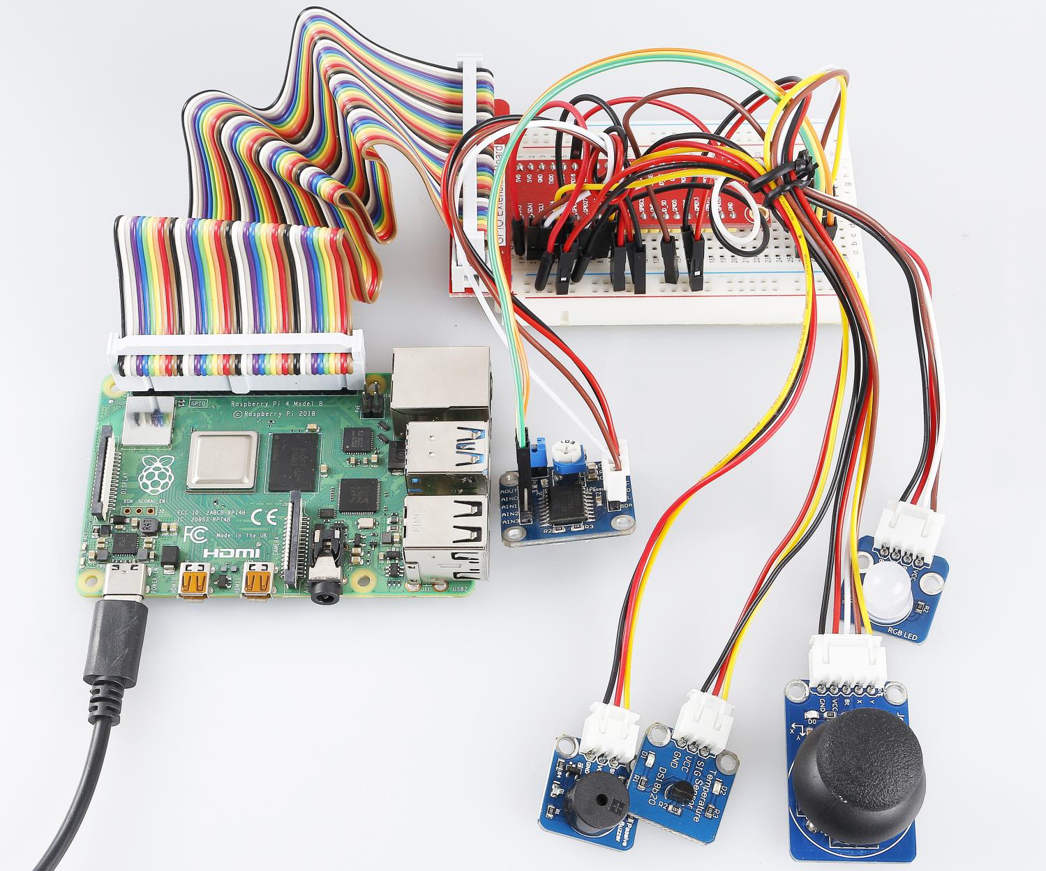
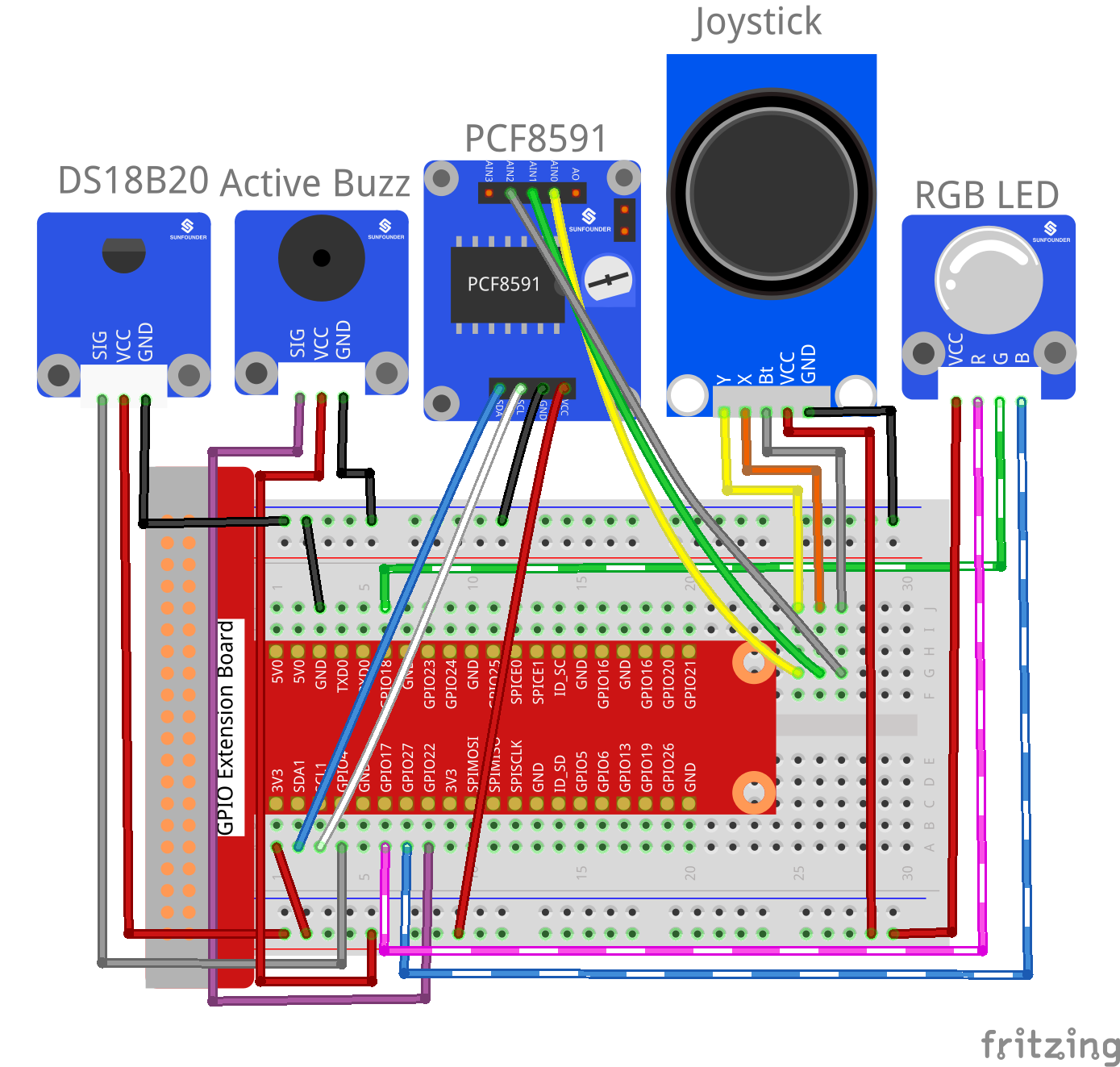
Step 1: Build the circuit.
Raspberry Pi |
GPIO Extension Board |
DS18B20 Module |
GPIO7 |
GPIO4 |
SIG |
3.3V |
3V3 |
VCC |
GND |
GND |
GND |
Raspberry Pi |
GPIO Extension Board |
PCF8591 Module |
SDA |
SDA1 |
SDA |
SCL |
SCL1 |
SCL |
3.3V |
3V3 |
VCC |
GND |
GND |
GND |
Joystick PS2 |
GPIO Extension Board |
PCF8591 Module |
Y |
* |
AIN0 |
X |
* |
AIN1 |
Bt |
* |
AIN2 |
VCC |
3V3 |
* |
GND |
GND |
* |
Raspberry Pi |
GPIO Extension Board |
RGB LED Module |
GPIO0 |
GPIO17 |
R |
GPIO1 |
GPIO18 |
G |
GPIO2 |
GPIO27 |
B |
3.3V |
3V3 |
VCC |
Raspberry Pi |
GPIO Extension Board |
Active Buzzer Module |
GPIO3 |
GPIO22 |
SIG |
3.3V |
3V3 |
VCC |
GND |
GND |
GND |
For C Users:
Step 2: Check the address of your sensor.
ls /sys/bus/w1/devices/
It may be like this:
28-031467805fff w1_bus_master1
Copy or write down 28-XXXXXXX. It is the address of your sensor.
Step 2: Change directory and edit.
cd /home/pi/SunFounder_SensorKit_for_RPi2/C/35_expand02/
nano temp_monitor.c
Find the function float tempRead(void), and the line “fd = open(XXXXXX)”. Replace “28-031467805ff” with your sensor address.
float tempRead(void)
{
float temp;
int i,j;
int fd;
int ret;

char buf[BUFSIZE];
char tempBuf[5];

fd = open("/sys/bus/w1/devices/28-031467805fff/w1_slave",O_RDONLY);

if(-1 == fd){
perror("open device file error");
return 1;
}
Save and exit.
Step 4: Compile.
gcc temp_monitor.c -lwiringPi
Note
If it does not work after running, or there is an error prompt wiringPi.h: No such file or directory, please refer to WiringPi to install it.
Step 5: Run.
sudo ./a.out
Code
#include <wiringPi.h>
#include <sys/types.h>
#include <sys/stat.h>
#include <fcntl.h>
#include <unistd.h>
#include <errno.h>
#include <stdlib.h>
#include <stdio.h>
#include <pcf8591.h>

#define     LedRed          0
#define     LedGreen        1
#define     LedBlue         2

#define     PCF                     120
#define             Beep            3
#define             BUFSIZE         128

typedef unsigned char uchar;
typedef unsigned int  uint;

static int sys_state = 1;

static int AIN0 = PCF + 0;
static int AIN1 = PCF + 1;
static int AIN2 = PCF + 2;

void beepInit(void)
{
    pinMode(Beep, OUTPUT);
}

void beep_on(void)
{
    digitalWrite(Beep, LOW);
}

void beep_off(void)
{
    digitalWrite(Beep, HIGH);
}

void beepCtrl(int t)
{
    beep_on();
    delay(t);
    beep_off();
    delay(t);
}

float tempRead(void)
{
    float temp;
    int i, j;
    int fd;
    int ret;

    char buf[BUFSIZE];
    char tempBuf[5];

    fd = open("/sys/bus/w1/devices/28-031590bf4aff/w1_slave", O_RDONLY);

    if(-1 == fd){
        perror("open device file error");
        return 1;
    }

    while(1){
        ret = read(fd, buf, BUFSIZE);
        if(0 == ret){
            break;
        }
        if(-1 == ret){
            if(errno == EINTR){
                continue;
            }
            perror("read()");
            close(fd);
            return 1;
        }
    }

    for(i=0;i<sizeof(buf);i++){
        if(buf[i] == 't'){
            for(j=0;j<sizeof(tempBuf);j++){
                tempBuf[j] = buf[i+2+j];
            }
        }
    }

    temp = (float)atoi(tempBuf) / 1000;

    close(fd);

    return temp;
}

void ledInit(void)
{
    pinMode(LedRed,   OUTPUT);
    pinMode(LedGreen, OUTPUT);
    pinMode(LedBlue,  OUTPUT);
}

/* */
void ledCtrl(int n, int state)
{
    digitalWrite(n, state);
}

void joystickquit(void)
{
    sys_state = 0;
    printf("interrupt occur !\n");
}

uchar get_joyStick_state(void)
{
    uchar tmp = 0;
    uchar xVal = 0, yVal = 0, zVal = 0;

    xVal = analogRead(AIN1);
    if(xVal >= 250){
        tmp = 1;
    }
    if(xVal <= 5){
        tmp = 2;
    }

    yVal = analogRead(AIN0);
    if(yVal >= 250){
        tmp = 4;
    }
    if(yVal <= 5){
        tmp = 3;
    }

    zVal = analogRead(AIN2);
    if(zVal <= 5){
        tmp = 5;
    }

    if(xVal-127<30 && xVal-127>-30 && yVal-127<30 && yVal-127>-30 && zVal>127){
        tmp = 0;
    }
// Uncomment this line to see the value of joystick.
//  printf("x = %d, y = %d, z = %d",xVal,yVal,zVal);
    return tmp;
}

int main(void)
{
    int i;
    uchar joyStick = 0;
    float temp;
    uchar low = 26, high = 30;

    if(wiringPiSetup() == -1){
        printf("setup wiringPi failed !");
        return 1;
    }

    pcf8591Setup(PCF, 0x48);
    ledInit();
    beepInit();

    printf("System is running...\n");

    while(1){
        flag:
        joyStick = get_joyStick_state();

        switch(joyStick){
            case 1 : --low;  break;
            case 2 : ++low;  break;
            case 3 : ++high; break;
            case 4 : --high; break;
            case 5 : joystickquit(); break;
            default: break;
        }

        if(low >= high){
            printf("Error, lower limit should be less than upper limit\n");
            goto flag;
        }

        printf("The lower limit of temperature : %d\n", low);
        printf("The upper limit of temperature : %d\n", high);

        temp = tempRead();

        printf("Current temperature : %0.3f\n", temp);

        if(temp < low){
            ledCtrl(LedBlue,  LOW);
            ledCtrl(LedRed,   HIGH);
            ledCtrl(LedGreen, LOW);
            for(i = 0;i < 3; i++){
                beepCtrl(400);
            }
        }
        if(temp >= low && temp < high){
            ledCtrl(LedBlue,  HIGH);
            ledCtrl(LedRed,   HIGH);
            ledCtrl(LedGreen, LOW);
        }
        if(temp >= high){
            ledCtrl(LedBlue,  HIGH);
            ledCtrl(LedRed,   LOW);
            ledCtrl(LedGreen, HIGH);
            for(i = 0;i < 3; i++){
                beepCtrl(80);
            }
        }

        if(sys_state == 0){
            ledCtrl(LedRed, LOW);
            ledCtrl(LedGreen, LOW);
            ledCtrl(LedBlue, LOW);
            beep_off();
            printf("SyStem will be off...\n");
            break;
        }
    }
    return 0;
}
For Python Users:
Step 2: Change directory.
cd /home/pi/SunFounder_SensorKit_for_RPi2/Python/
Step 4: Run.
sudo python3 35_temp_monitor.py
Code
#!/usr/bin/env python3
import RPi.GPIO as  GPIO
import importlib
import time
import sys

# BOARD pin numbering
LedR        =       11
LedG        =       12
LedB        =       13
Buzz        =       15

#ds18b20 = '28-031590bf4aff'
#location = '/sys/bus/w1/devices/' + ds18b20 + '/w1_slave'

joystick    =       importlib.import_module('15_joystick_PS2')
ds18b20             =       importlib.import_module('26_ds18b20')
beep                =       importlib.import_module('10_active_buzzer')
rgb                 =       importlib.import_module('02_rgb_led')

joystick.setup()
ds18b20.setup()
beep.setup(Buzz)
rgb.setup(LedR, LedG, LedB)

color = {'Red':0xFF0000, 'Green':0x00FF00, 'Blue':0x0000FF}

def setup():
    global lowl, highl
    lowl = 29
    highl = 31

def edge():
    global lowl, highl
    temp = joystick.direction()
    if temp == 'Pressed':
        destroy()
        quit()
    if temp == 'up' and lowl < highl-1:
        highl += 1
    if temp == 'down' and lowl >= -5:
        highl -= 1
    if temp == 'right' and highl <= 125:
        lowl += 1
    if temp == 'left' and lowl < highl-1:
        lowl -= 1

def loop():
    while True:
        edge()
        temp = ds18b20.read()
        print ('The lower limit of temperature : ', lowl)
        print ('The upper limit of temperature : ', highl)
        print ('Current temperature : ', temp)
        if float(temp) < float(lowl):
            rgb.setColor(color['Blue'])
            for i in range(0, 3):
                beep.beep(0.5)
        if temp >= float(lowl) and temp < float(highl):
            rgb.setColor(color['Green'])
        if temp >= float(highl):
            rgb.setColor(color['Red'])
            for i in range(0, 3):
                beep.beep(0.1)

def destroy():
    beep.destroy()
    joystick.destroy()
    ds18b20.destroy()
    rgb.destroy()

if __name__ == "__main__":
    try:
        setup()
        loop()
    except KeyboardInterrupt:
        destroy()
Now, you can pull the shaft of the joystick left and right to set the upper limit value, and up and down to set the lower limit value. Then, if the ambient temperature reaches the upper limit value or lower limit value, the buzzer will beep in a different frequency to warn.