Lesson 5 Laser Emitter Module
Introduction
Laser is widely used in medical treatment, military, and other fields due to its good directivity and energy concentration.
Required Components
1 * Raspberry Pi
1 * Breadboard
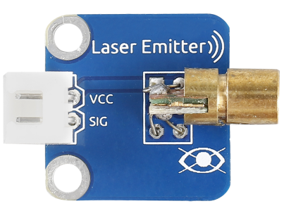
1 * Laser Emitter module
1 * 2-Pin anti-reverse cable
Experimental Principle
A laser is a device that emits light through a process of optical amplification based on the stimulated emission of electromagnetic radiation. Lasers differ from other sources of light because they emit light coherently.
Spatial coherence allows a laser to be focused to a tight spot, enabling applications like laser cutting and lithography, and a laser beam to stay narrow over long distances (collimation), enabling applications like laser pointers. Lasers can also have high temporal coherence which allows them to have a very narrow spectrum, i.e., they only emit light of a single color. And its temporal coherence can be used to produce pulses of light—as short as a femtosecond.
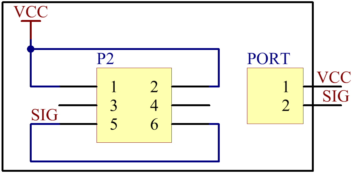
The schematic diagram of the module is as shown below:
Experimental Procedures
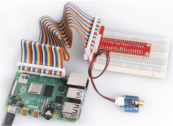
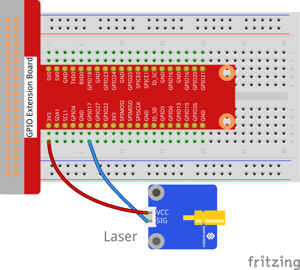
Step 1: Build the circuit.
Raspberry Pi |
GPIO Extension Board |
Laser Emitter Module |
3.3V |
3V3 |
VCC |
GPIO0 |
GPIO17 |
SIG |
For C Users:
Step 2: Change directory.
cd /home/pi/SunFounder_SensorKit_for_RPi2/C/05_laser/
Step 3: Compile.
gcc laser.c -lwiringPi
Note
If it does not work after running, or there is an error prompt wiringPi.h: No such file or directory, please refer to WiringPi to install it.
Step 4: Run.
sudo ./a.out
Code
#include <wiringPi.h>
#include <stdio.h>

#define LaserPin    0

int main(void)
{
    if(wiringPiSetup() == -1){ //when initialize wiring failed,print messageto screen
        printf("setup wiringPi failed !");
        return 1;
    }
    //printf("linker LedPin : GPIO %d(wiringPi pin)\n",LedPin); //when initialize wiring successfully,print message to screen

    pinMode(LaserPin, OUTPUT);

    while(1){
        digitalWrite(LaserPin, HIGH);
        delay(500);
        digitalWrite(LaserPin, LOW);
        delay(500);
    }

    return 0;
}
For Python Users:
Step 2: Change directory.
cd /home/pi/SunFounder_SensorKit_for_RPi2/Python/
Step 3: Run.
sudo python3 05_laser.py
Code
#!/usr/bin/env python3
import RPi.GPIO as GPIO
import time

LedPin = 11    # pin11

def setup():
    GPIO.setmode(GPIO.BOARD)       # Numbers GPIOs by physical location
    GPIO.setup(LedPin, GPIO.OUT)   # Set LedPin's mode is output
    GPIO.output(LedPin, GPIO.HIGH) # Set LedPin high(+3.3V) to off led

def loop():
    while True:
        #'...Laser on'
        GPIO.output(LedPin, GPIO.LOW)  # led on
        time.sleep(0.5)
        #'Laser off...'
        GPIO.output(LedPin, GPIO.HIGH) # led off
        time.sleep(0.5)

def destroy():
    GPIO.output(LedPin, GPIO.HIGH)     # led off
    GPIO.cleanup()                     # Release resource

if __name__ == '__main__':     # Program start from here
    setup()
    try:
        loop()
    except KeyboardInterrupt:  # When 'Ctrl+C' is pressed, the child program destroy() will be  executed.
        destroy()
Now you can see the module send out Morse signals.
Note
DO NOT look directly at the laser head. It can cause great harm to your eyes. You can point the laser beam to the table and see the light spot flashing on the table.