Lesson 6 Button Module
Introduction
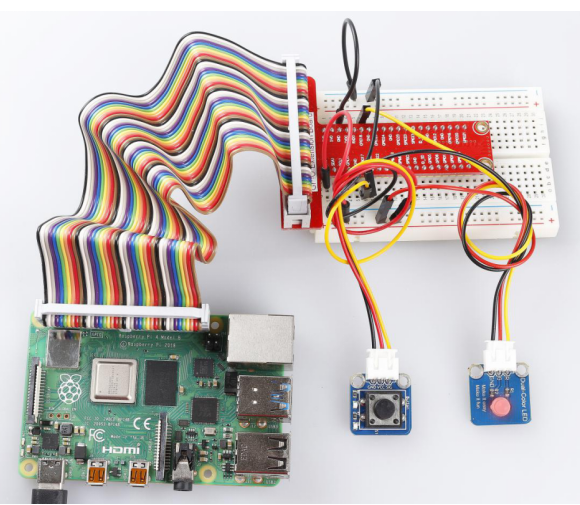
In this lesson, we will use button module to control a dual-color LED module.
Required Components
1 * Raspberry Pi
1 * Breadboard
Several Jumper wires
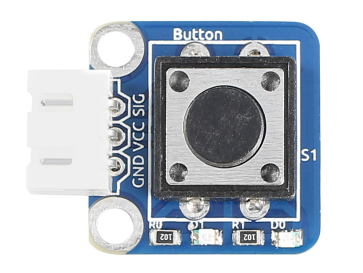
1 * Button module
1 * Dual-color LED module
2 * 3-Pin anti-reverse cable
Experimental Principle
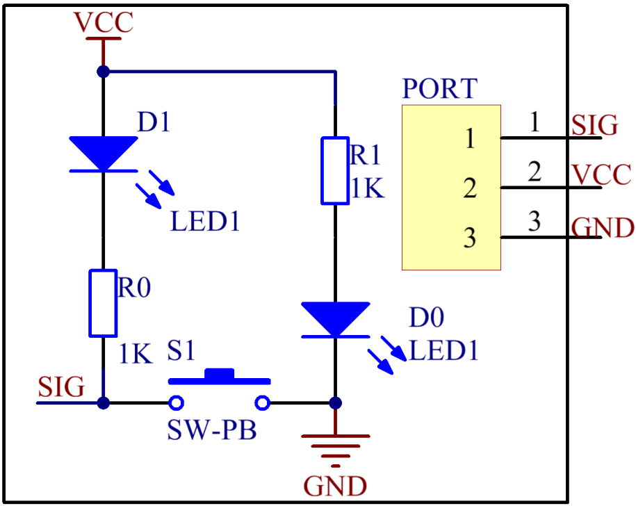
Use a normally open button as an input device of Raspberry Pi. When the button is pressed, the General Purpose Input/Output (GPIO) connected to the button will change to low level (0V). You can detect the state of the GPIO through programming. That is, if the GPIO turns into low level, it means the button is pressed, so you can run the corresponding code. In this experiment, we will print a string on the screen and control an LED.
The schematic diagram of the module is as shown below:
Experimental Procedures
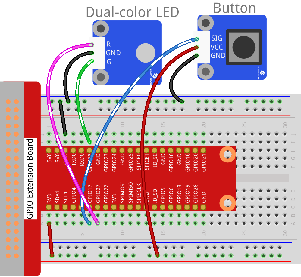
Step 1: Build the circuit.
Raspberry Pi |
GPIO Extension Board |
Button Module |
GPIO0 |
GPIO17 |
SIG |
3.3V |
3V3 |
VCC |
GND |
GND |
GND |
Raspberry Pi |
GPIO Extension Board |
Dual-Color LED Module |
GPIO1 |
GPIO18 |
R |
GND |
GND |
GND |
GPIO2 |
GPIO27 |
G |
For C Users:
Step 2: Change directory.
cd /home/pi/SunFounder_SensorKit_for_RPi2/C/06_button/
Step 3: Compile.
gcc button.c -lwiringPi
Note
If it does not work after running, or there is an error prompt wiringPi.h: No such file or directory, please refer to WiringPi to install it.
Step 4: Run.
sudo ./a.out
Code
#include <wiringPi.h>
#include <stdio.h>

#define BtnPin              0
#define Gpin                1
#define Rpin                2

void LED(char* color)
{
    pinMode(Gpin, OUTPUT);
    pinMode(Rpin, OUTPUT);
    if (color == "RED")
    {
        digitalWrite(Rpin, HIGH);
        digitalWrite(Gpin, LOW);
    }
    else if (color == "GREEN")
    {
        digitalWrite(Rpin, LOW);
        digitalWrite(Gpin, HIGH);
    }
    else
        printf("LED Error");
}

int main(void)
{
    if(wiringPiSetup() == -1){ //when initialize wiring failed,print messageto screen
        printf("setup wiringPi failed !");
        return 1;
    }

    pinMode(BtnPin, INPUT);
    LED("GREEN");

    while(1){
        if(0 == digitalRead(BtnPin)){
            delay(10);
            if(0 == digitalRead(BtnPin)){
                LED("RED");
                printf("Button is pressed\n");
            }
        }
        else if(1 == digitalRead(BtnPin)){
            delay(10);
            if(1 == digitalRead(BtnPin)){
                while(!digitalRead(BtnPin));
                LED("GREEN");
            }
        }
    }
    return 0;
}
For Python Users:
Step 2: Change directory.
cd /home/pi/SunFounder_SensorKit_for_RPi2/Python/
Step 3: Run.
sudo python3 06_button.py
Code
#!/usr/bin/env python3
import RPi.GPIO as GPIO

BtnPin = 11
Gpin   = 12
Rpin   = 13

def setup():
    GPIO.setmode(GPIO.BOARD)       # Numbers GPIOs by physical location
    GPIO.setup(Gpin, GPIO.OUT)     # Set Green Led Pin mode to output
    GPIO.setup(Rpin, GPIO.OUT)     # Set Red Led Pin mode to output
    GPIO.setup(BtnPin, GPIO.IN, pull_up_down=GPIO.PUD_UP)    # Set BtnPin's mode is input, and pull up to high level(3.3V)
    GPIO.add_event_detect(BtnPin, GPIO.BOTH, callback=detect, bouncetime=200)

def Led(x):
    if x == 0:
        GPIO.output(Rpin, 1)
        GPIO.output(Gpin, 0)
    if x == 1:
        GPIO.output(Rpin, 0)
        GPIO.output(Gpin, 1)

def detect(chn):
    Led(GPIO.input(BtnPin))

def loop():
    while True:
        pass

def destroy():
    GPIO.output(Gpin, GPIO.HIGH)       # Green led off
    GPIO.output(Rpin, GPIO.HIGH)       # Red led off
    GPIO.cleanup()                     # Release resource

if __name__ == '__main__':     # Program start from here
    setup()
    try:
        loop()
    except KeyboardInterrupt:  # When 'Ctrl+C' is pressed, the child program destroy() will be  executed.
        destroy()
The LED on the module will emit green light. If you press the button, “Button pressed” will be printed on the screen and the LED will emit red light. If you release the button, “Button released” will be printed on the screen and the LED will flash green again.