Lesson 17 Hall Sensor
Introduction
Based on Hall Effect, a Hall sensor is a one that varies its output voltage in response to a magnetic field. Hall sensors are used for proximity switching, positioning, speed detection, and current sensing applications.
Hall sensors can be categorized into linear (analog) Hall sensors and switch Hall sensors. A switch Hall sensor consists of voltage regulator, Hall element, differential amplifier, Schmitt trigger, and output terminal and it outputs digital values. A linear Hall sensor consists of Hall element, linear amplifier, and emitter follower and it outputs analog values. If you add a comparator to a linear (analog) Hall sensor it will be able to output both analog and digital signals.
Required Components
1 * Raspberry Pi
1 * Breadboard
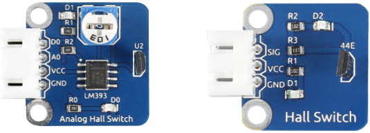
1 * Analog Hall Switch module
1 * Dual-color LED module
1 * Switch hall module
1 * PCF8591
2 * 3-Pin anti-reverse cable
1 * 4-Pin anti-reverse cable
Several Jumper wires
Experimental Principles
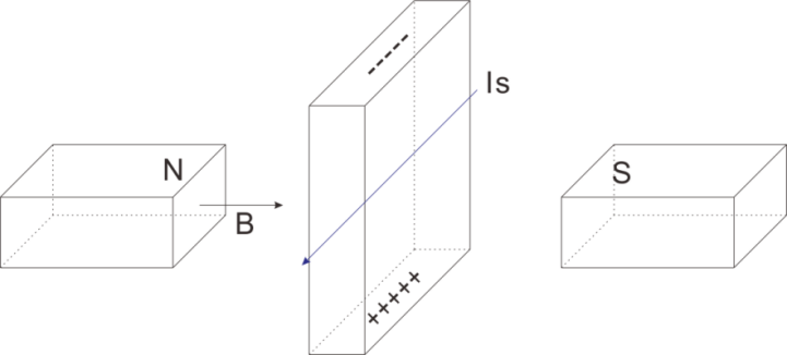
Hall Effect
Hall Effect is a kind of electromagnetic effect. It was discovered by Edwin Hall in 1879 when he was researching conductive mechanism about metals. The effect is seen when a conductor is passed through a uniform magnetic field. The natural electron drift of the charge carriers causes the magnetic field to apply a Lorentz force (the force exerted on a charged particle in an electromagnetic field) to these charge carriers. The result is what is seen as a charge separation, with a buildup of either positive or negative charges on the bottom or on the top of the plate.
Hall sensor
A Hall sensor is a kind of magnetic field sensor based on it.
Electricity carried through a conductor will produce a magnetic field that varies with current, and a Hall sensor can be used to measure the current without interrupting the circuit. Typically, the sensor is integrated with a wound core or permanent magnet that surrounds the conductor to be measured.
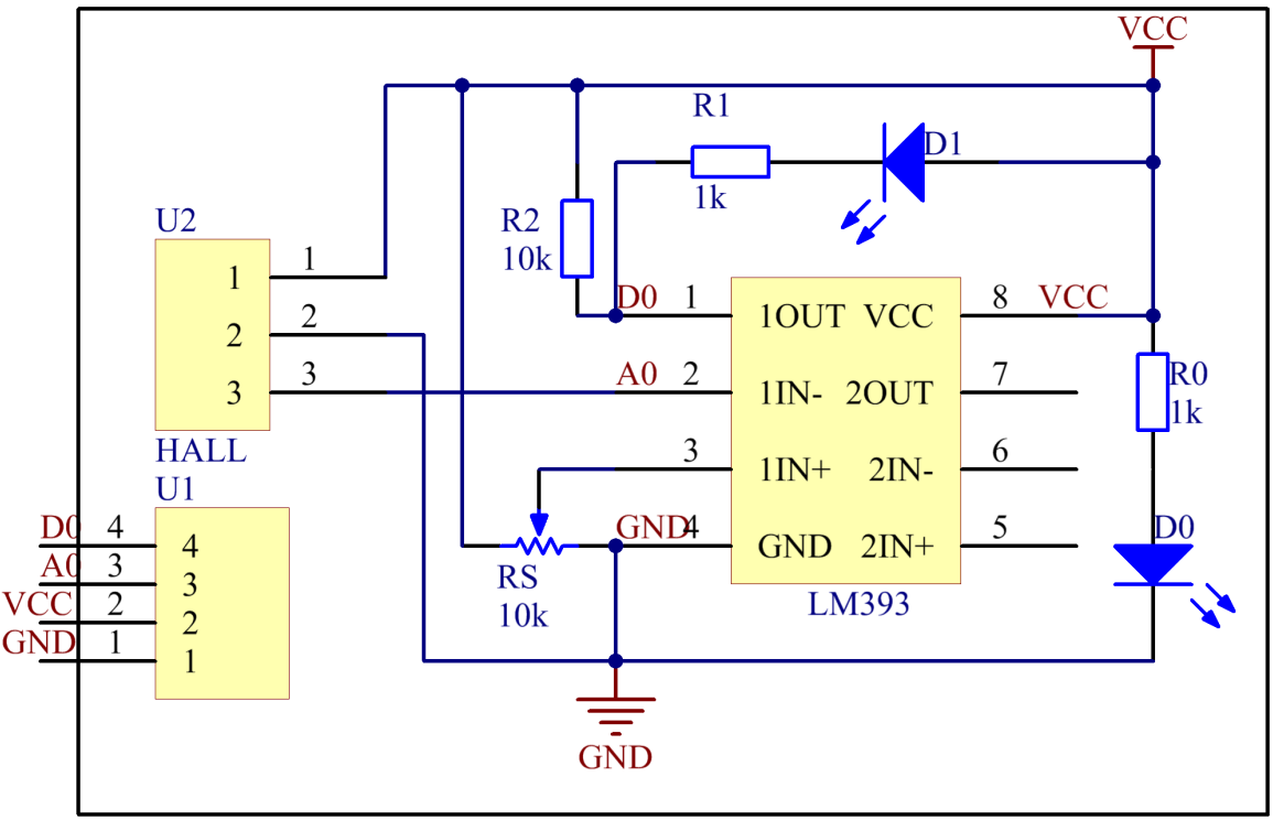
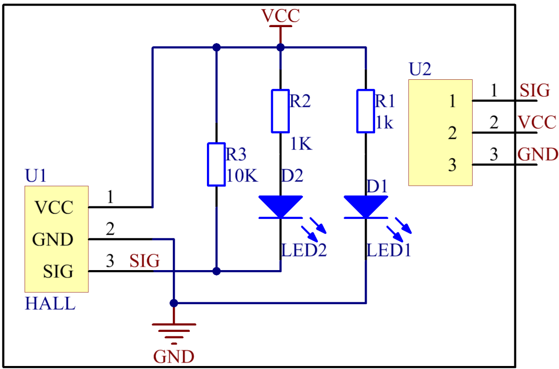
The schematic diagram of the analog Hall sensor module:
The schematic diagram of the Switch hall module:
Experimental Procedures
For switch Hall sensor, take the following steps.
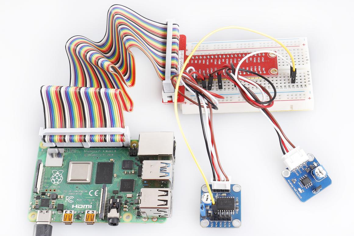
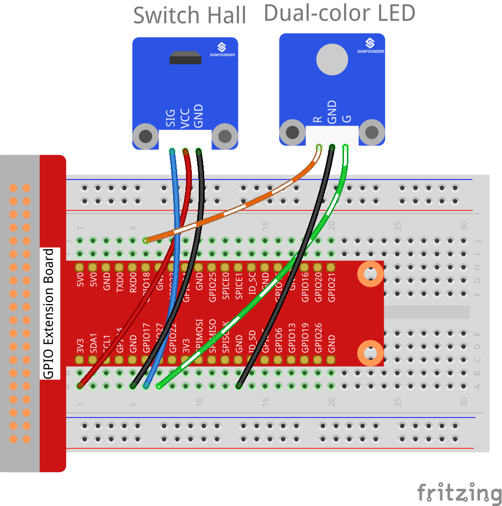
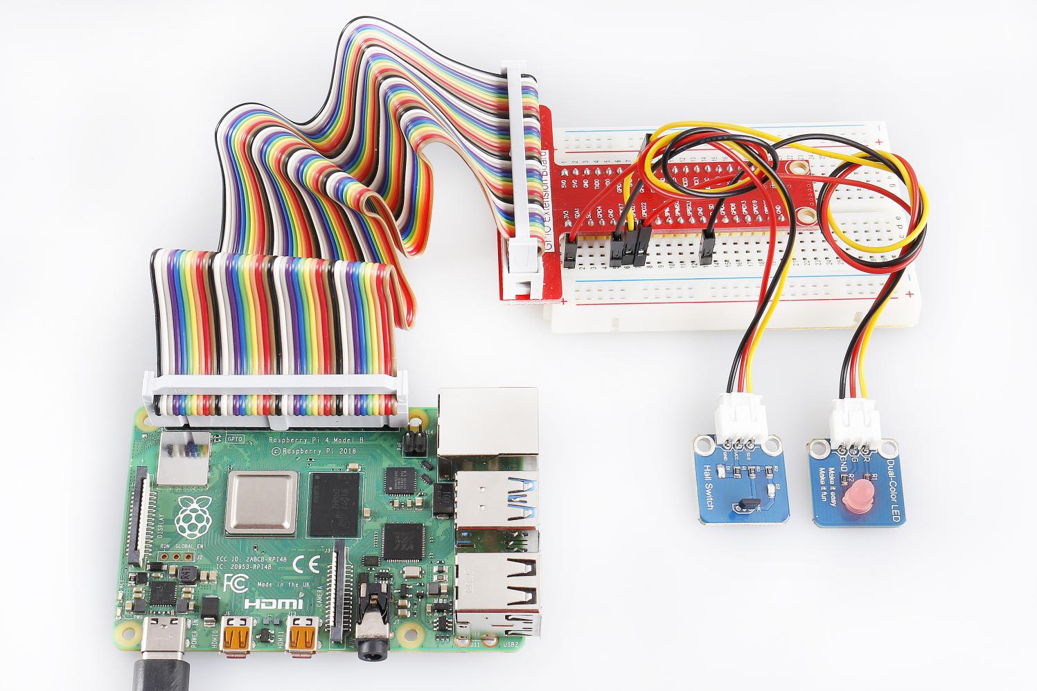
Step 1: Build the circuit.
Raspberry Pi |
GPIO Extension Board |
Switch Hall Module |
GPIO0 |
GPIO17 |
SIG |
3.3V |
3V3 |
VCC |
GND |
GND |
GND |
Raspberry Pi |
GPIO Extension Board |
Dual-color LED Module |
GPIO1 |
GPIO18 |
R |
GND |
GND |
GND |
GPIO2 |
GPIO27 |
G |
For C Users:
Step 2: Change directory.
cd /home/pi/SunFounder_SensorKit_for_RPi2/C/17_switch_hall/
Step 3: Compile.
gcc switch_hall.c -lwiringPi
Note
If it does not work after running, or there is an error prompt wiringPi.h: No such file or directory, please refer to WiringPi to install it.
Step 4: Run.
sudo ./a.out
Code
#include <wiringPi.h>
#include <stdio.h>

#define HallPin             0
#define Gpin                2
#define Rpin                1

void LED(char* color)
{
    pinMode(Gpin, OUTPUT);
    pinMode(Rpin, OUTPUT);
    if (color == "RED")
    {
        digitalWrite(Rpin, HIGH);
        digitalWrite(Gpin, LOW);
    }
    else if (color == "GREEN")
    {
        digitalWrite(Rpin, LOW);
        digitalWrite(Gpin, HIGH);
    }
    else
        printf("LED Error");
}

int main(void)
{
    if(wiringPiSetup() == -1){ //when initialize wiring failed,print messageto screen
        printf("setup wiringPi failed !");
        return 1;
    }

    pinMode(HallPin, INPUT);
    LED("GREEN");

    while(1){
        if(0 == digitalRead(HallPin)){
            delay(10);
            if(0 == digitalRead(HallPin)){
                LED("RED");
                printf("Detected magnetic materials \n");
            }
        }
        else if(1 == digitalRead(HallPin)){
            delay(10);
            if(1 == digitalRead(HallPin)){
                while(!digitalRead(HallPin));
                LED("GREEN");
            }
        }
    }
    return 0;
}
For Python Users:
Step 2: Change directory.
cd /home/pi/SunFounder_SensorKit_for_RPi2/Python/
Step 3: Run.
sudo python3 17_switch_hall.py
Code
#!/usr/bin/env python3
import RPi.GPIO as GPIO

HallPin = 11
Gpin   = 13
Rpin   = 12

def setup():
    GPIO.setmode(GPIO.BOARD)       # Numbers GPIOs by physical location
    GPIO.setup(Gpin, GPIO.OUT)     # Set Green Led Pin mode to output
    GPIO.setup(Rpin, GPIO.OUT)     # Set Red Led Pin mode to output
    GPIO.setup(HallPin, GPIO.IN, pull_up_down=GPIO.PUD_UP)    # Set BtnPin's mode is input, and pull up to high level(3.3V)
    GPIO.add_event_detect(HallPin, GPIO.BOTH, callback=detect, bouncetime=200)

def Led(x):
    if x == 0:
        GPIO.output(Rpin, 1)
        GPIO.output(Gpin, 0)
    if x == 1:
        GPIO.output(Rpin, 0)
        GPIO.output(Gpin, 1)

def Print(x):
    if x == 0:
        print ('    ***********************************')
        print ('    *   Detected magnetic materials   *')
        print ('    ***********************************')

def detect(chn):
    Led(GPIO.input(HallPin))
    Print(GPIO.input(HallPin))

def loop():
    while True:
        pass

def destroy():
    GPIO.output(Gpin, GPIO.HIGH)       # Green led off
    GPIO.output(Rpin, GPIO.HIGH)       # Red led off
    GPIO.cleanup()                     # Release resource

if __name__ == '__main__':     # Program start from here
    setup()
    try:
        loop()
    except KeyboardInterrupt:  # When 'Ctrl+C' is pressed, the child program destroy() will be  executed.
        destroy()
Put a magnet close to the Switch Hall sensor. Then a string “Detected magnetic materials” will be printed on the screen and the LED will light up.
For Analog Hall Switch, take the following steps.
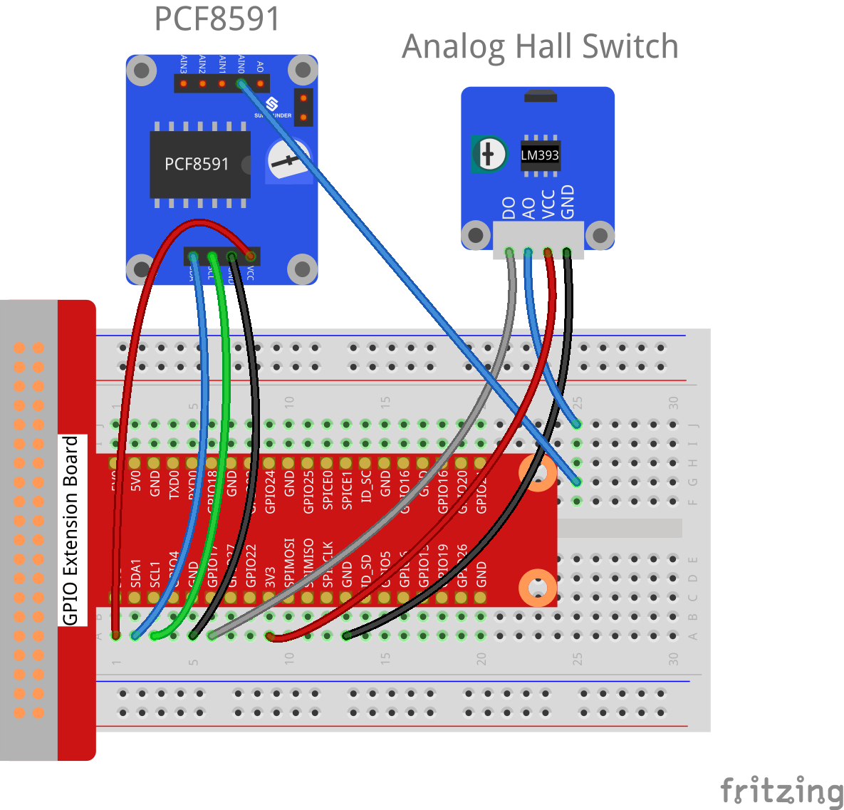
Step 1: Build the circuit.
Raspberry Pi |
GPIO Extension Board |
PCF8591 module |
SDA |
SDA1 |
SDA |
SCL |
SCL1 |
SCL |
3.3V |
3V3 |
VCC |
GND |
GND |
GND |
Analog Hall Switch |
GPIO Extension Board |
PCF8591 module |
DO |
GPIO17 |
* |
AO |
* |
AIN0 |
VCC |
3V3 |
VCC |
GND |
GND |
GND |
For C Users:
Step 2: Change directory.
cd /home/pi/SunFounder_SensorKit_for_RPi2/C/17_analog_hall_switch/
Step 3: Compile.
gcc analog_hall_switch.c -lwiringPi
Step 4: Run.
sudo ./a.out
Code
#include <stdio.h>
#include <wiringPi.h>
#include <pcf8591.h>

#define PCF       120

int main (void)
{
    int res, tmp, status;
    wiringPiSetup ();
    // Setup pcf8591 on base pin 120, and address 0x48
    pcf8591Setup (PCF, 0x48);
    status = 0;
    while(1) // loop forever
    {
        res = analogRead(PCF + 0);
        printf("Current intensity of magnetic field : %d\n", res);
        if (res - 133 < 5 || res - 133 > -5)
            tmp = 0;
        if (res < 128) tmp = -1;
        if (res > 138) tmp =  1;
        if (tmp != status)
        {
            switch(tmp)
            {
                case 0:
                    printf("\n*****************\n"  );
                    printf(  "* Magnet: None. *\n"  );
                    printf(  "*****************\n\n");
                    break;
                case -1:
                    printf("\n******************\n"  );
                    printf(  "* Magnet: North. *\n"  );
                    printf(  "******************\n\n");
                    break;
                case 1:
                    printf("\n******************\n"  );
                    printf(  "* Magnet: South. *\n"  );
                    printf(  "******************\n\n");
                    break;
            }
            status = tmp;
        }
        delay (200);
    }
    return 0 ;
}
For Python Users:
Step 2: Change directory.
cd /home/pi/SunFounder_SensorKit_for_RPi2/Python/
Step 3: Run.
sudo python3 17_analog_hall_switch.py
Code
#/usr/bin/env python3
import RPi.GPIO as GPIO
import PCF8591 as ADC
import time

def setup():
    ADC.setup(0x48)

def Print(x):
    if x == 0:
        print ('')
        print ('*************')
        print ('* No Magnet *')
        print ('*************')
        print ('')
    if x == 1:
        print ('')
        print ('****************')
        print ('* Magnet North *')
        print ('****************')
        print ('')
    if x == -1:
        print ('')
        print ('****************')
        print ('* Magnet South *')
        print ('****************')
        print ('')

def loop():
    status = 0
    while True:
        res = ADC.read(0)
        print ('Current intensity of magnetic field : ', res)
        if res - 133 < 5 and res - 133 > -5:
            tmp = 0
        if res < 128:
            tmp = -1
        if res > 138:
            tmp = 1
        if tmp != status:
            Print(tmp)
            status = tmp
        time.sleep(0.2)

if __name__ == '__main__':
    setup()
    loop()
Now “Current intensity of magnetic field : xxx ” will be displayed on the screen. Put the magnet close to the analog Hall sensor, with the north magnetic pole towards the sensor, and then ” Magnet: North.” will be displayed. Move the magnet away, and ” Magnet: None.” will be printed. If the magnet approaches the sensor with the south magnetic pole towards it, ” Magnet: South.” will be printed on the screen.
Note
Pin D0 of the Analog Hall Sensor will output “0” only when the south pole of the magnet approaches it, otherwise it will output “1”.