Lesson 12 Photo-interrupter
Introduction
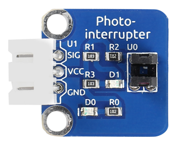
A photo-interrupter (as shown below) is a sensor with a light-emitting component and light-receiving component packaged and placed on face-to-face. It applies the principle that light is interrupted when an object passes through the sensor. Therefore, photo-interrupters are widely used in speed measurement.
Required Components
1 * Raspberry Pi
1 * Breadboard
1 * Dual-color LED module
1 * Photo-interrupter module
2 * 3-Pin anti-reverse cable
Experimental Principle
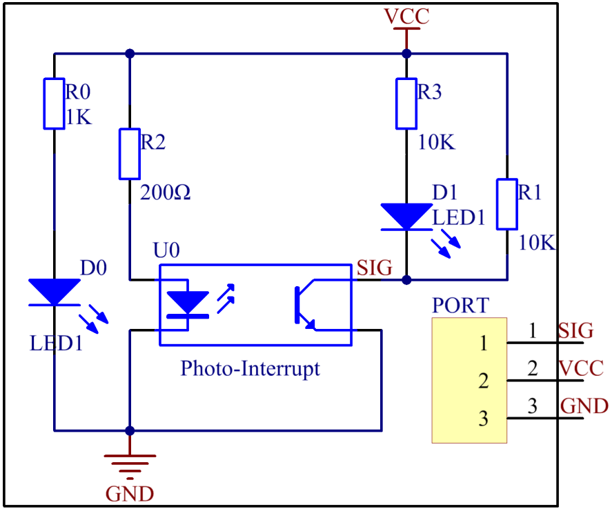
Basically a photo-interrupter consists of two parts: transmitter and receiver. The transmitter (e.g., an LED or a laser) emits light and then the light goes to the receiver. If that light beam between the transmitter and receiver is interrupted by an obstacle, the receiver will detect no incident light even for a moment and the output level will change. In this experiment, we will turn an LED on or off by using this change. The schematic diagram:
Experimental Procedures
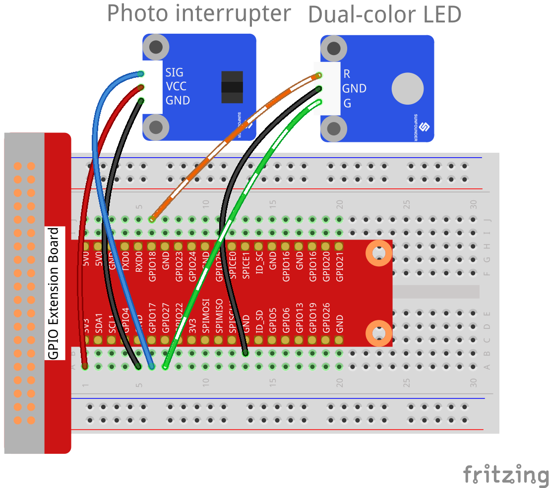
Step 1: Build the circuit.
Raspberry Pi |
GPIO Extension Board |
Photo-interrupter Module |
GPIO0 |
GPIO17 |
SIG |
3.3V |
3V3 |
VCC |
GND |
GND |
GND |
Raspberry Pi |
GPIO Extension Board |
Dual-color LED Module |
GPIO1 |
GPIO18 |
R |
GND |
GND |
GND |
GPIO2 |
GPIO27 |
G |
For C Users:
Step 2: Change directory.
cd /home/pi/SunFounder_SensorKit_for_RPi2/C/12_photo_interrupter/
Step 3: Compile.
gcc photo_interrupter.c -lwiringPi
Note
If it does not work after running, or there is an error prompt wiringPi.h: No such file or directory, please refer to WiringPi to install it.
Step 4: Run.
sudo ./a.out
Code
#include <wiringPi.h>
#include <stdio.h>

#define LBPin               0  // light break pin set to GPIO0
#define Gpin                2
#define Rpin                1

void LED(int color)
{
    pinMode(Gpin, OUTPUT);
    pinMode(Rpin, OUTPUT);
    if (color == 0){
        digitalWrite(Rpin, HIGH);
        digitalWrite(Gpin, LOW);
    }
    else if (color == 1){
        digitalWrite(Rpin, LOW);
        digitalWrite(Gpin, HIGH);
    }
}

void Print(int x){
    if ( x == 0 ){
        printf("Light was blocked\n");
    }
}

int main(void){

    if(wiringPiSetup() == -1){ //when initialize wiring failed,print messageto screen
        printf("setup wiringPi failed !");
        return 1;
    }

    pinMode(LBPin, INPUT);
    int temp;
    while(1){
        //Reverse the input of LBPin
        if ( digitalRead(LBPin) == 0 ){
            temp = 1;
        }
        if ( digitalRead(LBPin) == 1 ){
            temp = 0;
        }

        LED(temp);
        Print(temp);
        delay(100);
    }
    return 0;
}
For Python Users:
Step 2: Change directory.
cd /home/pi/SunFounder_SensorKit_for_RPi2/Python/
Step 3: Run.
sudo python3 12_photo_interrupter.py
Code
#!/usr/bin/env python3
import RPi.GPIO as GPIO

PIPin  = 11
Gpin   = 13
Rpin   = 12

def setup():
    GPIO.setmode(GPIO.BOARD)       # Numbers GPIOs by physical location
    GPIO.setup(Gpin, GPIO.OUT)     # Set Green Led Pin mode to output
    GPIO.setup(Rpin, GPIO.OUT)     # Set Red Led Pin mode to output
    GPIO.setup(PIPin, GPIO.IN, pull_up_down=GPIO.PUD_UP)    # Set BtnPin's mode is input, and pull up to high level(3.3V)
    GPIO.add_event_detect(PIPin, GPIO.BOTH, callback=detect, bouncetime=200)

def Led(x):
    if x == 0:
        GPIO.output(Rpin, 1)
        GPIO.output(Gpin, 0)
    if x == 1:
        GPIO.output(Rpin, 0)
        GPIO.output(Gpin, 1)
        print ('Light was blocked')

def detect(chn):
    Led(GPIO.input(PIPin))

def loop():
    while True:
        pass

def destroy():
    GPIO.output(Gpin, GPIO.HIGH)       # Green led off
    GPIO.output(Rpin, GPIO.HIGH)       # Red led off
    GPIO.cleanup()                     # Release resource

if __name__ == '__main__':     # Program start from here
    setup()
    try:
        loop()
    except KeyboardInterrupt:  # When 'Ctrl+C' is pressed, the child program destroy() will be  executed.
        destroy()
Now the LED will light up green. Stick a piece of paper in the gap of photo interrupter. Then “Light was blocked” will be printed on the screen and the LED will flash red. Remove the paper, and the LED will turn green again.