Lesson 34 Tracking Sensor
Introduction
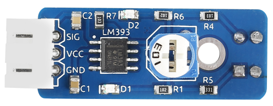
The infrared tracking sensor uses a TRT5000 sensor. The blue LED of TRT5000 is the emission tube and after electrified it emits infrared light invisible to human eye. The black part of the sensor is for receiving; the resistance of the resistor inside changes with the infrared light received.
Required Components
1 * Raspberry Pi
1 * Breadboard
1 * Tracking sensor module
1 * 3-Pin anti-reverse cable
Experimental Principle
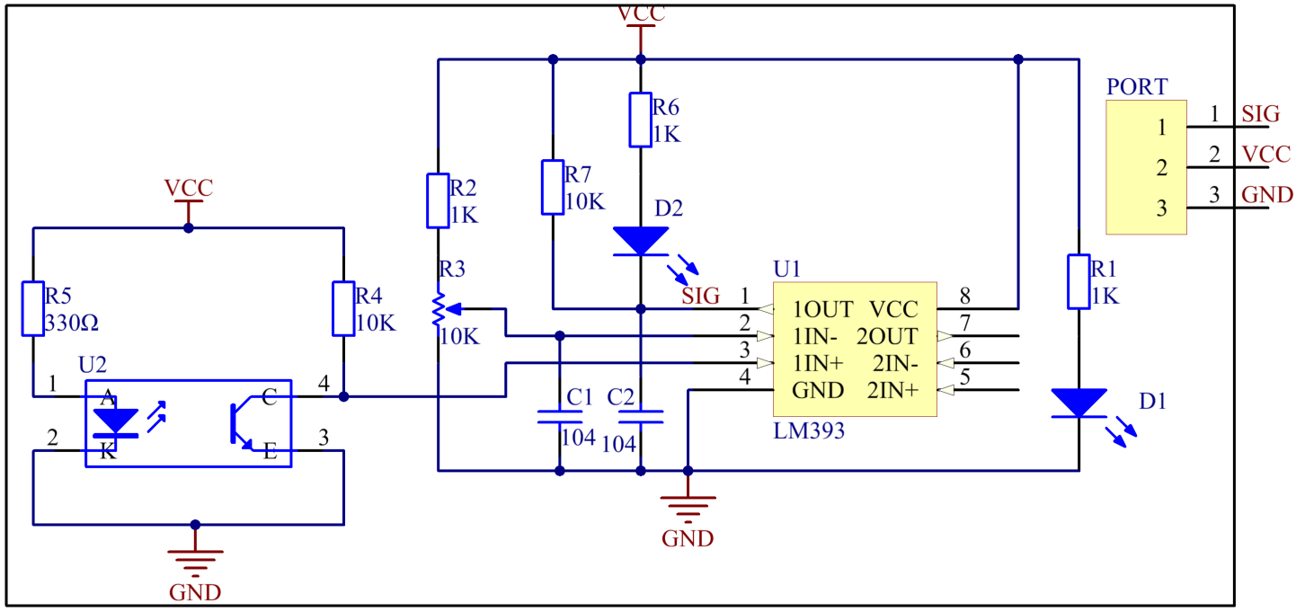
When the infrared transmitter emits rays to a piece of paper, if the rays shine on a white surface, they will be reflected and received by the receiver, and pin SIG will output low level; If the rays encounter black lines, they will be absorbed, thus the receiver gets nothing, and pin SIG will output high level. The schematic diagram of the module is as shown below:
Experimental Procedures
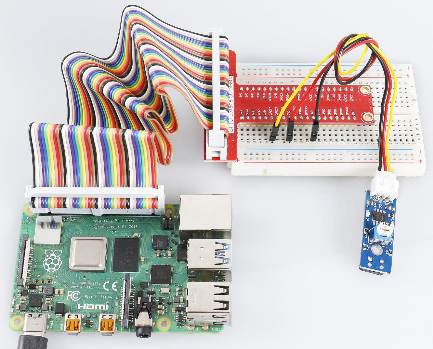
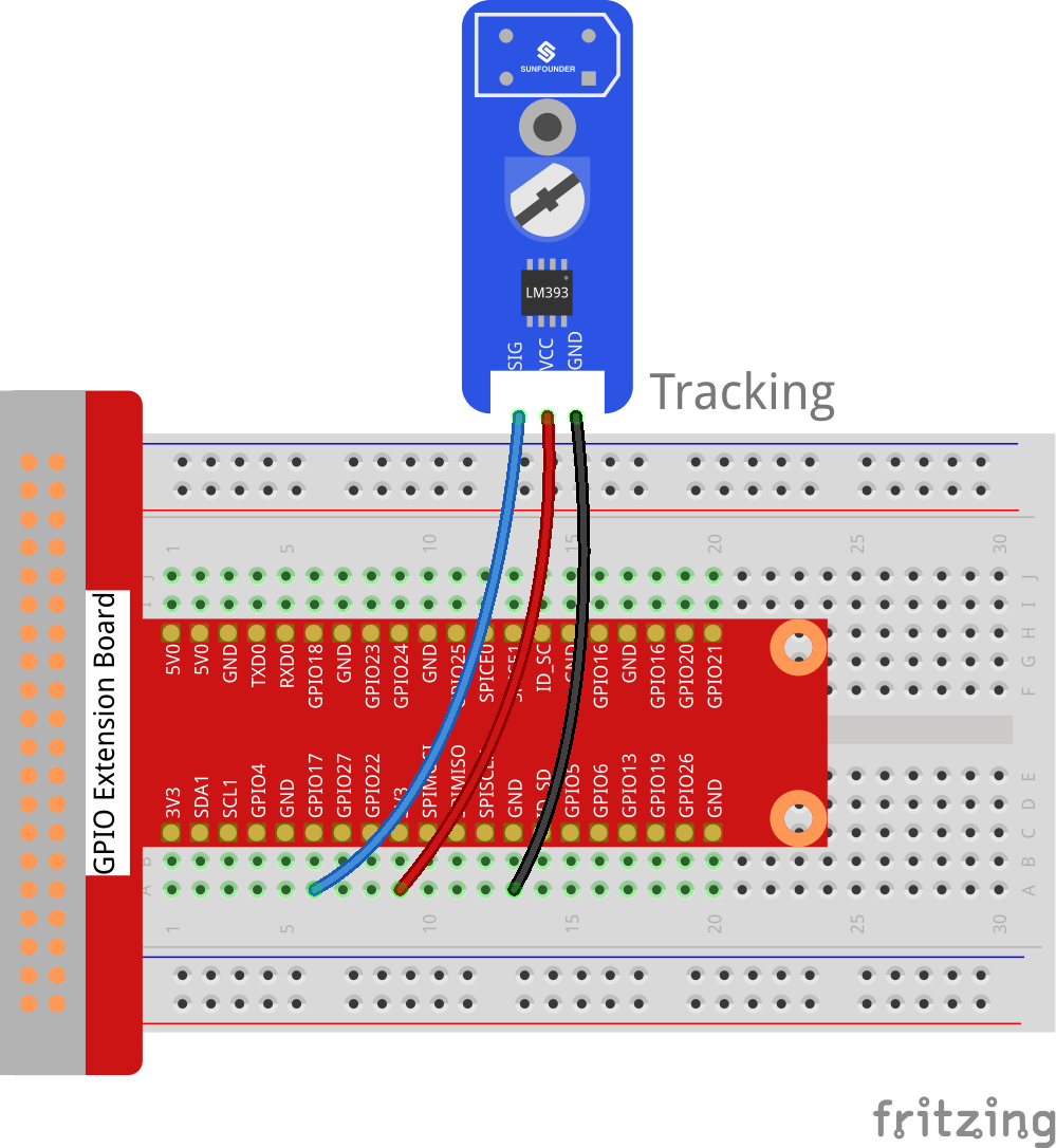
Step 1: Build the circuit.
Raspberry Pi |
GPIO Extension Board |
Tracking Sensor Module |
GPIO0 |
GPIO17 |
SIG |
3.3V |
3V3 |
VCC |
GND |
GND |
GND |
For C Users:
Step 2: Change directory.
cd /home/pi/SunFounder_SensorKit_for_RPi2/C/34_tracking/
Step 3: Compile.
gcc tracking.c -lwiringPi
Note
If it does not work after running, or there is an error prompt wiringPi.h: No such file or directory, please refer to WiringPi to install it.
Step 4: Run.
sudo ./a.out
Code
#include <wiringPi.h>
#include <stdio.h>

#define TrackSensorPin    0
#define LedPin            1

int main(void)
{
    if(wiringPiSetup() == -1){ //when initialize wiring failed,print messageto screen
        printf("setup wiringPi failed !");
        return 1;
    }

    pinMode(TrackSensorPin, INPUT);
    pinMode(LedPin,  OUTPUT);

    while(1){
        if(digitalRead(TrackSensorPin) == LOW){
            printf("White line is detected\n");
            digitalWrite(LedPin, LOW);     //led on
            delay(100);
            digitalWrite(LedPin, HIGH);    //led off
        }
        else{
            printf("...Black line is detected\n");
            delay(100);
        }
    }

    return 0;
}
For Python Users:
Step 2: Change directory.
cd /home/pi/SunFounder_SensorKit_for_RPi2/Python/
Step 3: Run.
sudo python3 34_tracking.py
Code
#!/usr/bin/env python3
import RPi.GPIO as GPIO
import time

TrackPin = 11
LedPin   = 12

def setup():
    GPIO.setmode(GPIO.BOARD)       # Numbers GPIOs by physical location
    GPIO.setup(LedPin, GPIO.OUT)   # Set LedPin's mode is output
    GPIO.setup(TrackPin, GPIO.IN, pull_up_down=GPIO.PUD_UP)
    GPIO.output(LedPin, GPIO.HIGH) # Set LedPin high(+3.3V) to off led

def loop():
    while True:
        if GPIO.input(TrackPin) == GPIO.LOW:
            print ('White line is detected')
            time.sleep(0.5)
            GPIO.output(LedPin, GPIO.LOW)  # led on
        else:
            print ('...Black line is detected')
            time.sleep(0.5)
            GPIO.output(LedPin, GPIO.HIGH) # led off

def destroy():
    GPIO.output(LedPin, GPIO.HIGH)     # led off
    GPIO.cleanup()                     # Release resource

if __name__ == '__main__':     # Program start from here
    setup()
    try:
        loop()
    except KeyboardInterrupt:  # When 'Ctrl+C' is pressed, the child program destroy() will be  executed.
        destroy()
When the tracking sensor encounters black lines, a string “Black Line is detected” will be printed on the screen.