Lesson 24 Touch Switch
Introduction
A touch sensor operate with the conductivity of human body. When you touch the metal on the base electrode of the transistor, the level of pin SIG will turn over.
Required Components
1 * Raspberry Pi
1 * Breadboard
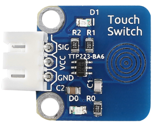
1 * Touch sensor module
1 * Dual-Color LED module
2 * 3-Pin anti-reverse cable
Experimental Principle
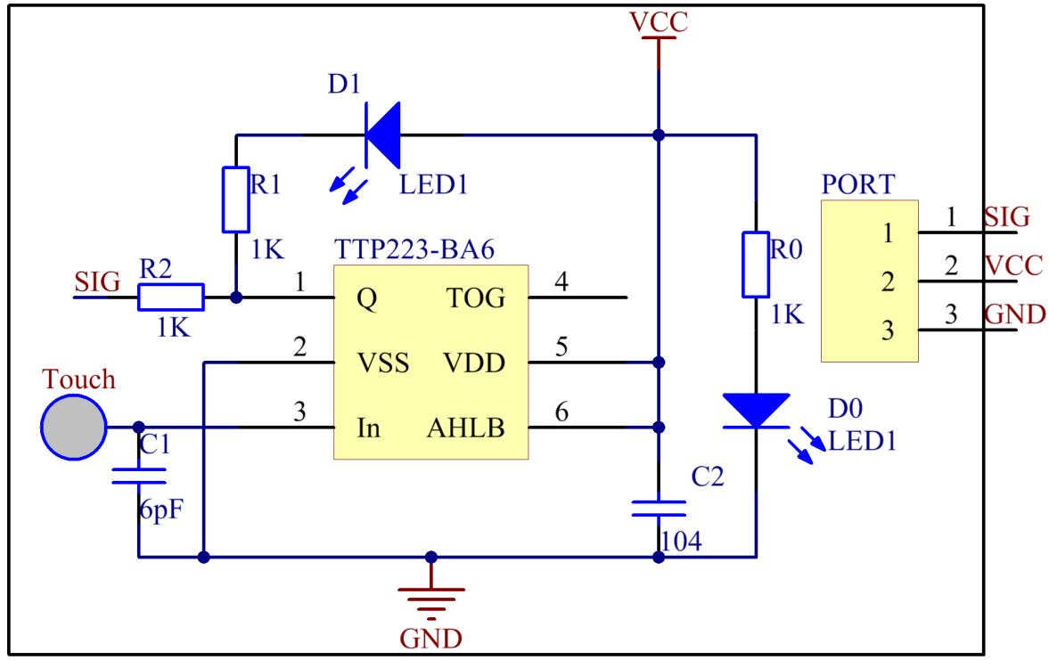
In this experiment, touch the base electrode of the transistor by fingers to make it conduct as human body itself is a kind of conductor and an antenna that can receive electromagnetic waves in the air. These electromagnetic wave signals collected from the human body are amplified by the transistor and processed by the comparator on the module to output steady signals. The schematic diagram:
Experimental Procedures
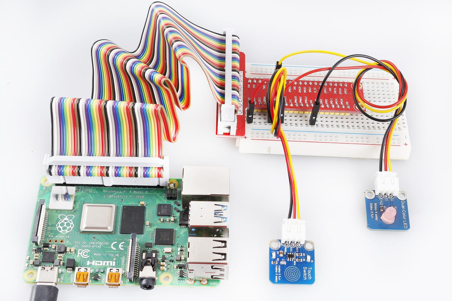
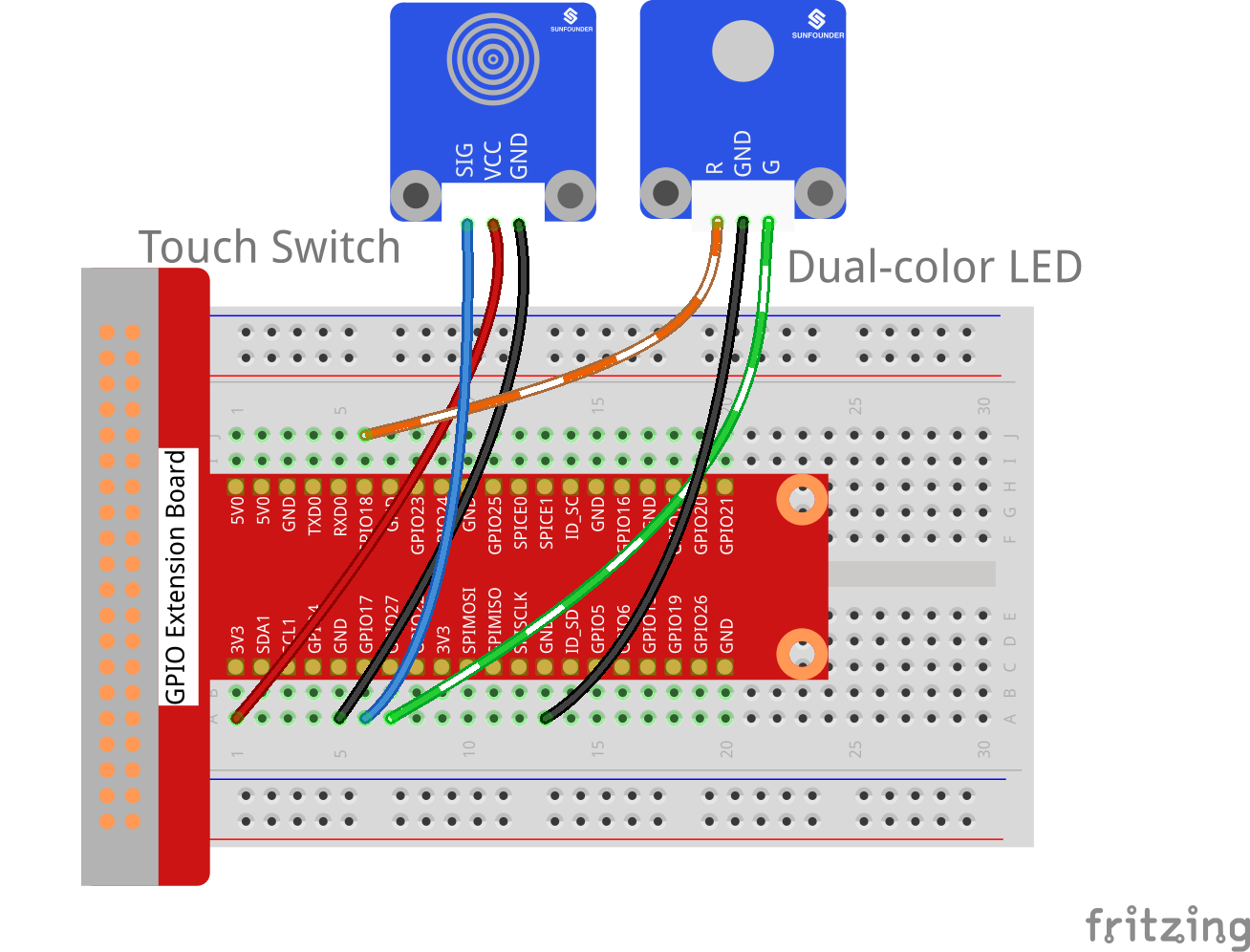
Step 1: Build the circuit.
Raspberry Pi |
GPIO Extension Board |
Touch Sensor Module |
GPIO0 |
GPIO17 |
SIG |
3.3V |
3V3 |
VCC |
GND |
GND |
GND |
Raspberry Pi |
GPIO Extension Board |
Dual-Color LED Module |
GPIO1 |
GPIO18 |
R |
GND |
GND |
GND |
GPIO2 |
GPIO27 |
G |
For C Users:
Step 2: Change directory.
cd /home/pi/SunFounder_SensorKit_for_RPi2/C/24_touch_switch/
Step 3: Compile.
gcc touch_switch.c -lwiringPi
Note
If it does not work after running, or there is an error prompt wiringPi.h: No such file or directory, please refer to WiringPi to install it.
Step 4: Run.
sudo ./a.out
Code
#include <wiringPi.h>
#include <stdio.h>

#define TouchPin    0
#define Gpin                2
#define Rpin                1

int tmp = 0;

void LED(int color)
{
    pinMode(Gpin, OUTPUT);
    pinMode(Rpin, OUTPUT);
    if (color == 0)
    {
        digitalWrite(Rpin, HIGH);
        digitalWrite(Gpin, LOW);
    }
    else if (color == 1)
    {
        digitalWrite(Rpin, LOW);
        digitalWrite(Gpin, HIGH);
    }
    else
        printf("LED Error");
}

void Print(int x){
    if (x != tmp){
        if (x == 0)
            printf("...ON\n");
        if (x == 1)
            printf("OFF..\n");
        tmp = x;
    }
}

int main(void)
{
    if(wiringPiSetup() == -1){ //when initialize wiring failed,print messageto screen
        printf("setup wiringPi failed !");
        return 1;
    }

    pinMode(TouchPin, INPUT);

    while(1){
        LED(digitalRead(TouchPin));
        Print(digitalRead(TouchPin));
    }
    return 0;
}
For Python Users:
Step 2: Change directory.
cd /home/pi/SunFounder_SensorKit_for_RPi2/Python/
Step 3: Run.
sudo python3 24_touch_switch.py
Code
#!/usr/bin/env python3
import RPi.GPIO as GPIO

TouchPin = 11
Gpin   = 13
Rpin   = 12

tmp = 0

def setup():
    GPIO.setmode(GPIO.BOARD)       # Numbers GPIOs by physical location
    GPIO.setup(Gpin, GPIO.OUT)     # Set Green Led Pin mode to output
    GPIO.setup(Rpin, GPIO.OUT)     # Set Red Led Pin mode to output
    GPIO.setup(TouchPin, GPIO.IN, pull_up_down=GPIO.PUD_UP)    # Set BtnPin's mode is input, and pull up to high level(3.3V)

def Led(x):
    if x == 0:
        GPIO.output(Rpin, 1)
        GPIO.output(Gpin, 0)
    if x == 1:
        GPIO.output(Rpin, 0)
        GPIO.output(Gpin, 1)

def Print(x):
    global tmp
    if x != tmp:
        if x == 0:
            print ('    **********')
            print ('    *     ON *')
            print ('    **********')

        if x == 1:
            print ('    **********')
            print ('    * OFF    *')
            print ('    **********')
        tmp = x

def loop():
    while True:
        Led(GPIO.input(TouchPin))
        Print(GPIO.input(TouchPin))

def destroy():
    GPIO.output(Gpin, GPIO.HIGH)       # Green led off
    GPIO.output(Rpin, GPIO.HIGH)       # Red led off
    GPIO.cleanup()                     # Release resource

if __name__ == '__main__':     # Program start from here
    setup()
    try:
        loop()
    except KeyboardInterrupt:  # When 'Ctrl+C' is pressed, the child program destroy() will be  executed.
        destroy()
Now, touch the metal disk, you can see the LED change its colors and “ON” and “OFF” printed on the screen.