Note
Hello, welcome to the SunFounder Raspberry Pi & Arduino & ESP32 Enthusiasts Community on Facebook! Dive deeper into Raspberry Pi, Arduino, and ESP32 with fellow enthusiasts.
Why Join?
Expert Support: Solve post-sale issues and technical challenges with help from our community and team.
Learn & Share: Exchange tips and tutorials to enhance your skills.
Exclusive Previews: Get early access to new product announcements and sneak peeks.
Special Discounts: Enjoy exclusive discounts on our newest products.
Festive Promotions and Giveaways: Take part in giveaways and holiday promotions.
👉 Ready to explore and create with us? Click [here] and join today!
Motor
Overview
In this lesson, you will learn how to use Motor, the working principle of which is that the energized coil is forced to rotate in the magnetic field then the rotor of the motor rotates accordingly on which the pinion gear drives the engine flywheel to rotate.1
Required Components
In this project, we need the following components.
It’s definitely convenient to buy a whole kit, here’s the link:
Name |
ITEMS IN THIS KIT |
LINK |
|---|---|---|
Elite Explorer Kit |
300+ |
You can also buy them separately from the links below.
COMPONENT INTRODUCTION |
PURCHASE LINK |
|---|---|
- |
|
- |
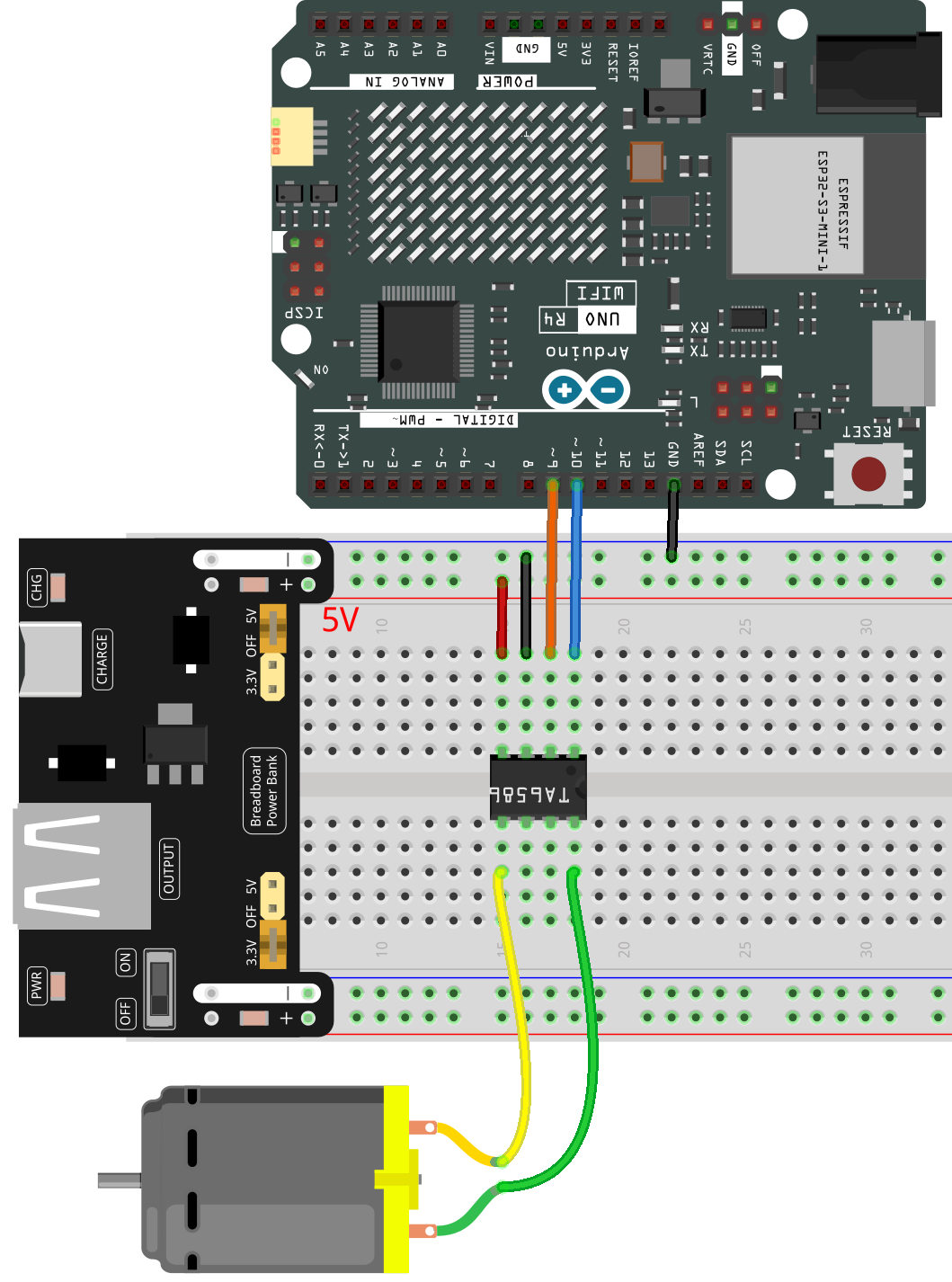
Wiring
In this example, we use Power Supply Module to power the anode and cathode of breadboard.
Note
The motor requires more power during operation, so please keep the power module connected to a charging cable when in use.
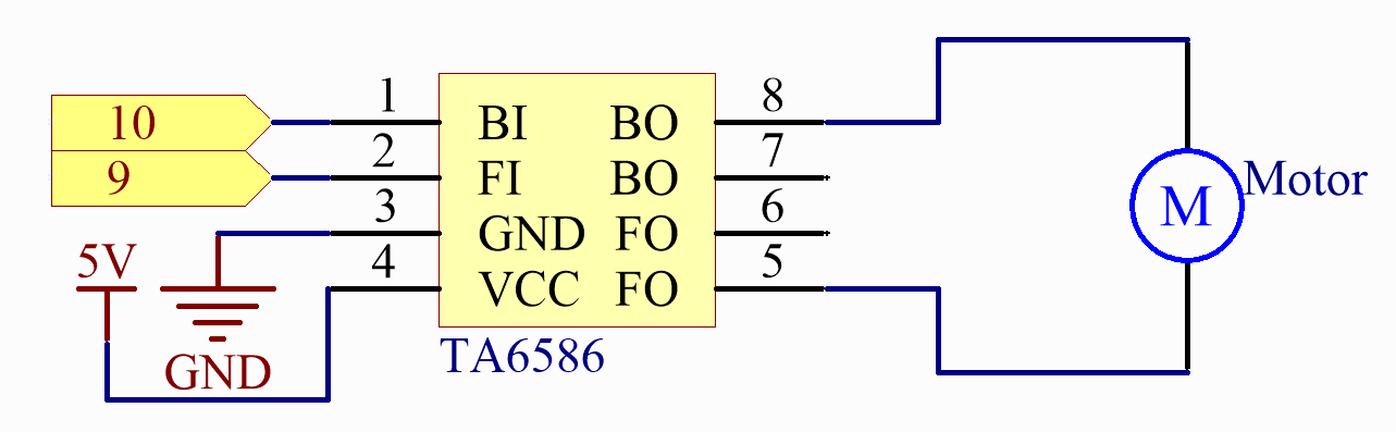
Schematic Diagram
Code
Note
You can open the file
24-motor.inounder the path ofelite-explorer-kit-main\basic_project\24-motordirectly.Or copy this code into Arduino IDE.
 1/*
 2  The code controls a motor using an Arduino Uno R4 and a TA6586 chip. It
 3  sets the rotation direction of the motor based on the user's serial input
 4  ('A' for clockwise and 'B' for anticlockwise). After performing the rotation
 5  for 3 seconds, the motor is stopped.
 6
 7  Board: Arduino Uno R4
 8  Component: Motor and TA6586 chip
 9*/
10
11// Pin definitions for motor control
12const int motorBI = 10;
13const int motorFI = 9;
14
15// Initialization function
16void setup() {
17  // Set motor control pins as OUTPUT
18  pinMode(motorBI, OUTPUT);
19  pinMode(motorFI, OUTPUT);
20
21  // Initialize serial communication and prompt user
22  Serial.begin(9600);
23  Serial.println("Please input 'A' or 'B' to select the motor rotate direction.");
24}
25
26// Main loop function
27void loop() {
28  // Check if there is available data on the serial port
29  if (Serial.available() > 0) {
30    int incomingByte = Serial.read(); // Read incoming data
31
32    // Determine motor direction based on user input
33    switch (incomingByte) {
34      case 'A':
35        clockwise(255); // Rotate motor clockwise
36        Serial.println("The motor rotates clockwise.");
37        break;
38      case 'B':
39        anticlockwise(255); // Rotate motor anticlockwise
40        Serial.println("The motor rotates anticlockwise.");
41        break;
42    }
43  }
44
45  delay(3000); // Wait for 3 seconds
46  stopMotor(); // Stop the motor
47}
48
49// Function to rotate the motor clockwise
50void clockwise(int Speed) {
51  analogWrite(motorBI, 0);
52  analogWrite(motorFI, Speed);
53}
54
55// Function to rotate the motor anticlockwise
56void anticlockwise(int Speed) {
57  analogWrite(motorBI, Speed);
58  analogWrite(motorFI, 0);
59}
60
61// Function to stop the motor
62void stopMotor() {
63  analogWrite(motorBI, 0);
64  analogWrite(motorFI, 0);
65}
After uploading the code to the UNO board, you can choose the motor’s rotation direction by typing “A” or “B” in the serial monitor.
Code Analysis
The motor can be driven by providing a voltage difference between the copper sheets at both sides of the motor. Therefore, you only need to write 0 for the voltage of one side of the copper sheet and 5V for the other side. Modify the written analog signal value to adjust the direction and speed.
// Function to rotate the motor clockwise
void clockwise(int Speed) {
  analogWrite(motorBI, 0);
  analogWrite(motorFI, Speed);
}

// Function to rotate the motor anticlockwise
void anticlockwise(int Speed) {
  analogWrite(motorBI, Speed);
  analogWrite(motorFI, 0);
}
In this example, Serial.Read() is used to control the direction of motor.
When you type 'A' in serial monitor, there calls the clockwise (255) function to make the motor rotate with the speed of 255. Input 'B', and the motor will rotate in reverse direction.
void loop() {
  // Check if there is available data on the serial port
  if (Serial.available() > 0) {
    int incomingByte = Serial.read(); // Read incoming data

    // Determine motor direction based on user input
    switch (incomingByte) {
      case 'A':
        clockwise(255); // Rotate motor clockwise
        Serial.println("The motor rotates clockwise.");
        break;
      case 'B':
        anticlockwise(255); // Rotate motor anticlockwise
        Serial.println("The motor rotates anticlockwise.");
        break;
    }
  }

  delay(3000); // Wait for 3 seconds
  stopMotor(); // Stop the motor
}