Note
Hello, welcome to the SunFounder Raspberry Pi & Arduino & ESP32 Enthusiasts Community on Facebook! Dive deeper into Raspberry Pi, Arduino, and ESP32 with fellow enthusiasts.
Why Join?
Expert Support: Solve post-sale issues and technical challenges with help from our community and team.
Learn & Share: Exchange tips and tutorials to enhance your skills.
Exclusive Previews: Get early access to new product announcements and sneak peeks.
Special Discounts: Enjoy exclusive discounts on our newest products.
Festive Promotions and Giveaways: Take part in giveaways and holiday promotions.
👉 Ready to explore and create with us? Click [here] and join today!
Joystick Module
Overview
A joystick is an input device consisting of a stick that pivots on a base and reports its angle or direction to the device it is controlling. Joysticks are often used to control video games and robots. A Joystick PS2 is used here.
Required Components
In this project, we need the following components.
It’s definitely convenient to buy a whole kit, here’s the link:
Name |
ITEMS IN THIS KIT |
LINK |
|---|---|---|
Elite Explorer Kit |
300+ |
You can also buy them separately from the links below.
COMPONENT INTRODUCTION |
PURCHASE LINK |
|---|---|
- |
|
Wiring
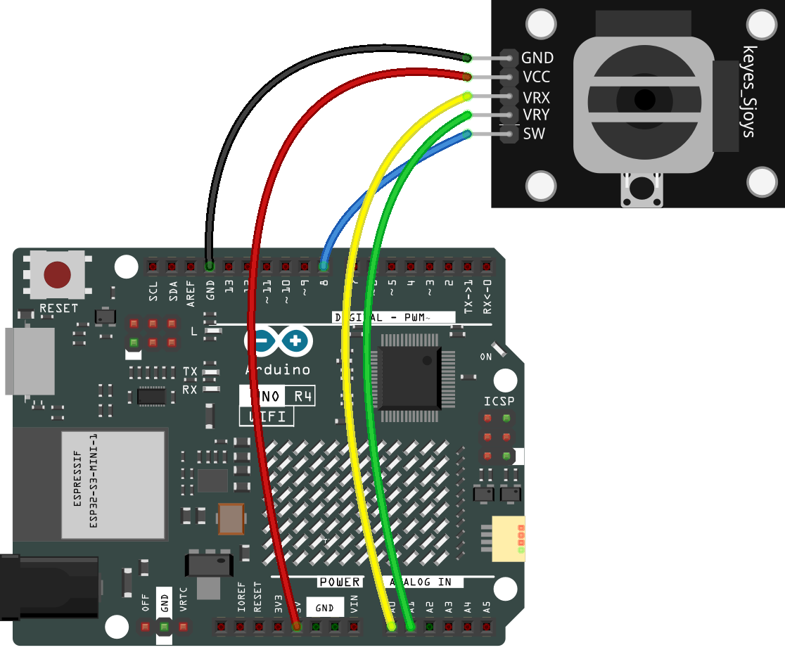
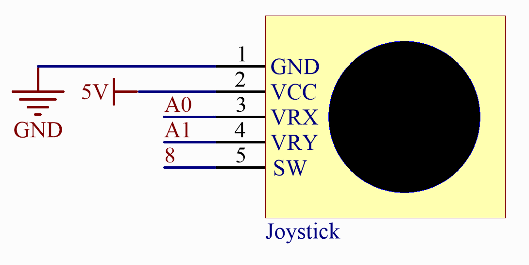
Schematic Diagram
This module has two analog outputs (corresponding to X,Y biaxial offsets).
In this experiment, we use the Uno board to detect the moving direction of the Joystick knob.
Code
Note
You can open the file
20-joystick.inounder the path ofelite-explorer-kit-main\basic_project\20-joystickdirectly.Or copy this code into Arduino IDE.
 1/*
 2  The code reads values from a joystick module and prints them on the serial monitor.
 3  The joystick module has two analog axes (X and Y), which are connected to Arduino
 4  pins A0 and A1. The decimal form of the X and Y axis values is read and displayed
 5  on the serial monitor.
 6
 7  Board: Arduino Uno R4
 8  Component: Joystick Module
 9*/
10
11const int xPin = A0;  //the VRX attach to
12const int yPin = A1;  //the VRY attach to
13const int swPin = 8;  //the SW attach to
14
15void setup() {
16  pinMode(swPin, INPUT_PULLUP);
17  Serial.begin(9600);
18}
19
20void loop() {
21  Serial.print("X: ");
22  Serial.print(analogRead(xPin), DEC);  // print the value of VRX in DEC
23  Serial.print("|Y: ");
24  Serial.print(analogRead(yPin), DEC);  // print the value of VRX in DEC
25  Serial.print("|Z: ");
26  Serial.println(digitalRead(swPin));  // print the value of SW
27  delay(50);
28}
Now, when you push the rocker, the coordinates of the X and Y axes displayed on the Serial Monitor will change accordingly. Pressing the button will also display the coordinate Z=0.
Code Analysis
The code is use the serial monitor to print the value of the VRX and VRY pins of the joystick ps2.
void loop()
{
    Serial.print("X: ");
    Serial.print(analogRead(xPin), DEC);  // print the value of VRX in DEC
    Serial.print("|Y: ");
    Serial.print(analogRead(yPin), DEC);  // print the value of VRX in DEC
    Serial.print("|Z: ");
    Serial.println(digitalRead(swPin));  // print the value of SW
    delay(50);
}