Note
Hello, welcome to the SunFounder Raspberry Pi & Arduino & ESP32 Enthusiasts Community on Facebook! Dive deeper into Raspberry Pi, Arduino, and ESP32 with fellow enthusiasts.
Why Join?
Expert Support: Solve post-sale issues and technical challenges with help from our community and team.
Learn & Share: Exchange tips and tutorials to enhance your skills.
Exclusive Previews: Get early access to new product announcements and sneak peeks.
Special Discounts: Enjoy exclusive discounts on our newest products.
Festive Promotions and Giveaways: Take part in giveaways and holiday promotions.
👉 Ready to explore and create with us? Click [here] and join today!
LED module
Just as printing “Hello, world!” is the first step in learning to program, using a program to drive an LED is the traditional introduction to learning physical programming.
Required Components
In this project, we need the following components.
It’s definitely convenient to buy a whole kit, here’s the link:
Name |
ITEMS IN THIS KIT |
LINK |
|---|---|---|
Elite Explorer Kit |
300+ |
You can also buy them separately from the links below.
COMPONENT INTRODUCTION |
PURCHASE LINK |
|---|---|
- |
|
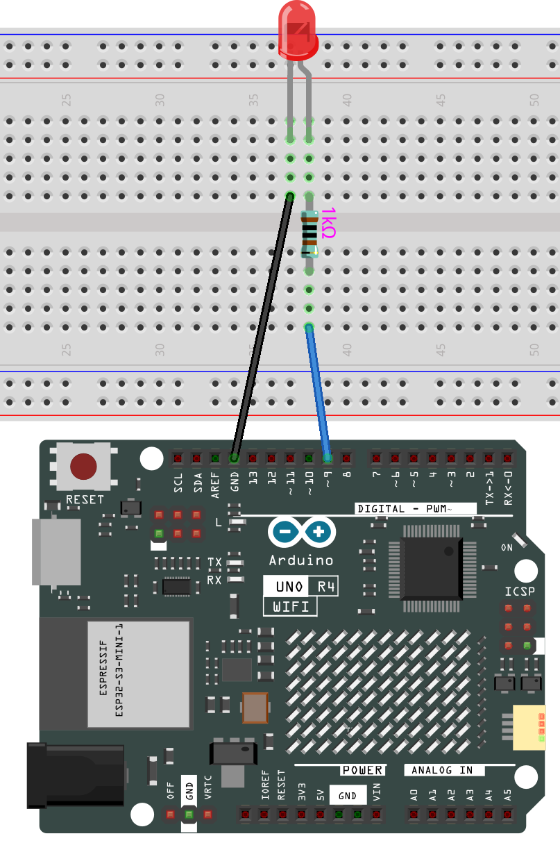
Wiring
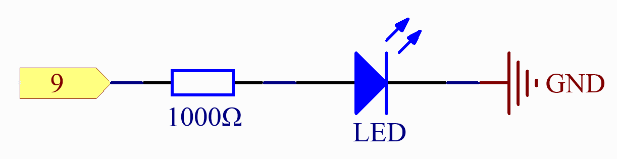
Schematic Diagram
Code
Note
You can open the file
10-led.inounder the path ofelite-explorer-kit-main\basic_project\10-led.Or copy this code into Arduino IDE.
 1/*
 2  The code is intended to blink an LED connected to digital pin 9 of an
 3  Arduino board. The LED turns on for half a second, then turns off for
 4  half a second, repeatedly.
 5
 6  Board: Arduino Uno R4
 7  Component: LED
 8*/
 9
10// Declare the pin number for the LED
11const int ledPin = 9;
12
13// Setup runs once when you press reset or power the board
14void setup() {
15  // Initialize the digital pin as an output
16  pinMode(ledPin, OUTPUT);
17}
18
19// Loop runs continuously after setup completes
20void loop() {
21  digitalWrite(ledPin, HIGH); // Turn the LED on
22  delay(500);                 // Pause for 500 milliseconds (half a second)
23  digitalWrite(ledPin, LOW);  // Turn the LED off
24  delay(500);                 // Pause for 500 milliseconds (half a second)
25}
After the code is uploaded successfully, you will see the LED connected to digital pin 9 of the Arduino board start to blink. The LED will turn on for half a second and then turn off for another half a second, repeating this cycle continuously as the program runs.
Code Analysis
Here, we connect the LED to the digital pin 9, so we need to declare an int variable called ledpin at the beginning of the program and assign a value of 9.
const int ledPin = 9;
Now, initialize the pin in the setup() function, where you need to initialize the pin to OUTPUT mode.
void setup() {
    pinMode(ledPin, OUTPUT);
}
In loop(), digitalWrite() is used to provide 5V high level signal for ledpin, which will cause voltage difference between LED pins and light LED up.
digitalWrite(ledPin, HIGH);
If the level signal is changed to LOW, the ledPin’s signal will be returned to 0 V to turn LED off.
digitalWrite(ledPin, LOW);
An interval between on and off is required to allow people to see the change,
so we use a delay(1000) code to let the controller do nothing for 1000 ms.
delay(1000);