Note
Hello, welcome to the SunFounder Raspberry Pi & Arduino & ESP32 Enthusiasts Community on Facebook! Dive deeper into Raspberry Pi, Arduino, and ESP32 with fellow enthusiasts.
Why Join?
Expert Support: Solve post-sale issues and technical challenges with help from our community and team.
Learn & Share: Exchange tips and tutorials to enhance your skills.
Exclusive Previews: Get early access to new product announcements and sneak peeks.
Special Discounts: Enjoy exclusive discounts on our newest products.
Festive Promotions and Giveaways: Take part in giveaways and holiday promotions.
👉 Ready to explore and create with us? Click [here] and join today!
Potentiometer
Overview
In this lesson, let’s see how to change the luminance of an LED by a potentiometer, and receive the data of the potentiometer in Serial Monitor to see its value change.
Required Components
In this project, we need the following components.
It’s definitely convenient to buy a whole kit, here’s the link:
Name |
ITEMS IN THIS KIT |
LINK |
|---|---|---|
Elite Explorer Kit |
300+ |
You can also buy them separately from the links below.
COMPONENT INTRODUCTION |
PURCHASE LINK |
|---|---|
- |
|
Wiring
Schematic Diagram
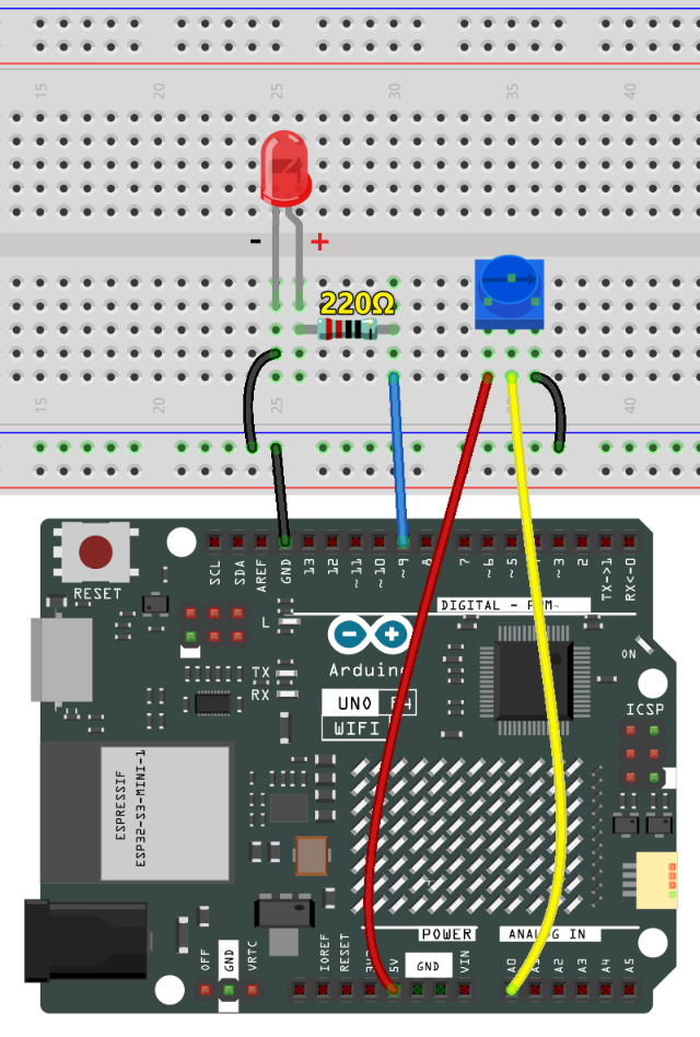
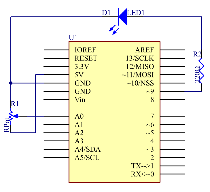
In this experiment, the potentiometer is used as voltage divider, meaning connecting devices to all of its three pins. Connect the middle pin of the potentiometer to pin A0 and the other two pins to 5V and GND respectively. Therefore, the voltage of the potentiometer is 0-5V. Spin the knob of the potentiometer, and the voltage at pin A0 will change. Then convert that voltage into a digital value (0-1024) with the AD converter in the control board. Through programming, we can use the converted digital value to control the brightness of the LED on the control board.
Code
Note
You can open the file
19-potentiometer.inounder the path ofelite-explorer-kit-main\basic_project\19-potentiometerdirectly.Or copy this code into Arduino IDE.
 1/*
 2  This code is for controlling the brightness of an LED using a potentiometer.
 3
 4  The code uses a potentiometer as an input device. It reads analog data from
 5  the potentiometer, scales the read value from a range of 0-1023 to 0-255,
 6  and then uses this scaled value to control the brightness of an LED. The raw
 7  and scaled values are also printed to the serial monitor for debugging or monitoring.
 8
 9  Board: Arduino Uno R4
10  Component: Potentiometer
11*/
12
13const int analogPin = 0;  // Analog input pin connected to the potentiometer
14const int ledPin = 9;     // Digital output pin connected to the LED
15
16int inputValue = 0;       // Variable to store the raw value from the potentiometer
17int outputValue = 0;      // Variable to store the scaled output value
18
19void setup() {
20  Serial.begin(9600);  // Initialize serial communication with a baud rate of 9600
21}
22
23void loop() {
24  inputValue = analogRead(analogPin);              // Read the analog value from the potentiometer
25  Serial.print("Input: ");                         // Print "Input: " to the serial monitor
26  Serial.println(inputValue);                      // Print the raw input value to the serial monitor
27
28  // Map the input value from a range of 0-1023 to a range of 0-255
29  outputValue = map(inputValue, 0, 1023, 0, 255);
30
31  Serial.print("Output: ");                        // Print "Output: " to the serial monitor
32  Serial.println(outputValue);                     // Print the scaled output value to the serial monitor
33
34  analogWrite(ledPin, outputValue);                // Control the LED brightness based on the scaled value
35  delay(1000);                                     // Wait for 1 second before the next loop iteration
36}
After uploading the code to the Uno board, you can open the serial monitor to observe the potentiometer’s read values. As you turn the potentiometer knob, the read value will change accordingly. The raw analog reading from the potentiometer will range from (0) to (1023). Simultaneously, the code scales this value to a range of (0) to (255), which is also displayed on the serial monitor. This scaled value is then used to control the brightness of the connected LED. The LED will become brighter or dimmer based on the scaled value. It’s worth noting that while the theoretical range of the potentiometer is (0) to (1023), the actual range may vary slightly due to hardware tolerances.
Code Analysis
Initialization and Setup (Setting Pin Modes and Initializing Serial Communication)
Before we get into the loop, we define which pins we’re using and initialize the serial communication.
const int analogPin = 0;  // Analog input pin connected to the potentiometer
const int ledPin = 9;     // Digital output pin connected to the LED

void setup() {
  Serial.begin(9600);  // Initialize serial communication with a baud rate of 9600
}
Reading Analog Input (Getting Data from Potentiometer)
In this segment, we read the analog data from the potentiometer and print it to the serial monitor.
inputValue = analogRead(analogPin);  // Read the analog value from the potentiometer
Serial.print("Input: ");             // Print "Input: " to the serial monitor
Serial.println(inputValue);          // Print the raw input value to the serial monitor
Mapping and Scaling (Converting Potentiometer Data)
We scale the raw data from the potentiometer, which is in the range of 0-1023, to a new range of 0-255.
map(value, fromLow, fromHigh, toLow, toHigh)is used to convert a number from one range to another. For example, if the value is within the range offromLowandfromHigh, it will be converted to a corresponding value within the range oftoLowandtoHigh, maintaining proportionality between the two ranges.In this case, since the LED pin (pin 9) has a range of 0-255, we need to map values in the range of 0-1023 to match that same scale of 0-255.
outputValue = map(inputValue, 0, 1023, 0, 255); // Map the input value to a new range
Controlling LED and Serial Output
Finally, we control the LED’s brightness based on the scaled value and print the scaled value for monitoring.
Serial.print("Output: ");                        // Print "Output: " to the serial monitor
Serial.println(outputValue);                     // Print the scaled output value to the serial monitor
analogWrite(ledPin, outputValue);                // Control the LED brightness based on the scaled value
delay(1000);