Note
Hello, welcome to the SunFounder Raspberry Pi & Arduino & ESP32 Enthusiasts Community on Facebook! Dive deeper into Raspberry Pi, Arduino, and ESP32 with fellow enthusiasts.
Why Join?
Expert Support: Solve post-sale issues and technical challenges with help from our community and team.
Learn & Share: Exchange tips and tutorials to enhance your skills.
Exclusive Previews: Get early access to new product announcements and sneak peeks.
Special Discounts: Enjoy exclusive discounts on our newest products.
Festive Promotions and Giveaways: Take part in giveaways and holiday promotions.
👉 Ready to explore and create with us? Click [here] and join today!
2.3 Colorful Light
In this project, we will delve into the fascinating world of additive color mixing using an RGB LED.
RGB LED combines three primary colors, namely Red, Green, and Blue, into a single package. These three LEDs share a common cathode pin, while each anode pin controls the intensity of the corresponding color.
By varying the electrical signal intensity applied to each anode, we can create a wide range of colors. For example, mixing high-intensity red and green light will result in yellow light, while combining blue and green light will produce cyan.
Through this project, we will explore the principles of additive color mixing and unleash our creativity by manipulating the RGB LED to display captivating and vibrant colors.
Required Components
In this project, we need the following components.
It’s definitely convenient to buy a whole kit, here’s the link:
Name |
ITEMS IN THIS KIT |
LINK |
|---|---|---|
ESP32 Starter Kit |
320+ |
You can also buy them separately from the links below.
COMPONENT INTRODUCTION |
PURCHASE LINK |
|---|---|
Available Pins
Here is a list of available pins on the ESP32 board for this project.
Available Pins |
IO13, IO12, IO14, IO27, IO26, IO25, IO33, IO32, IO15, IO2, IO0, IO4, IO5, IO18, IO19, IO21, IO22, IO23 |
Schematic
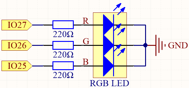
The PWM pins pin27, pin26 and pin25 control the Red, Green and Blue pins of the RGB LED respectively, and connect the common cathode pin to GND. This allows the RGB LED to display a specific color by superimposing light on these pins with different PWM values.
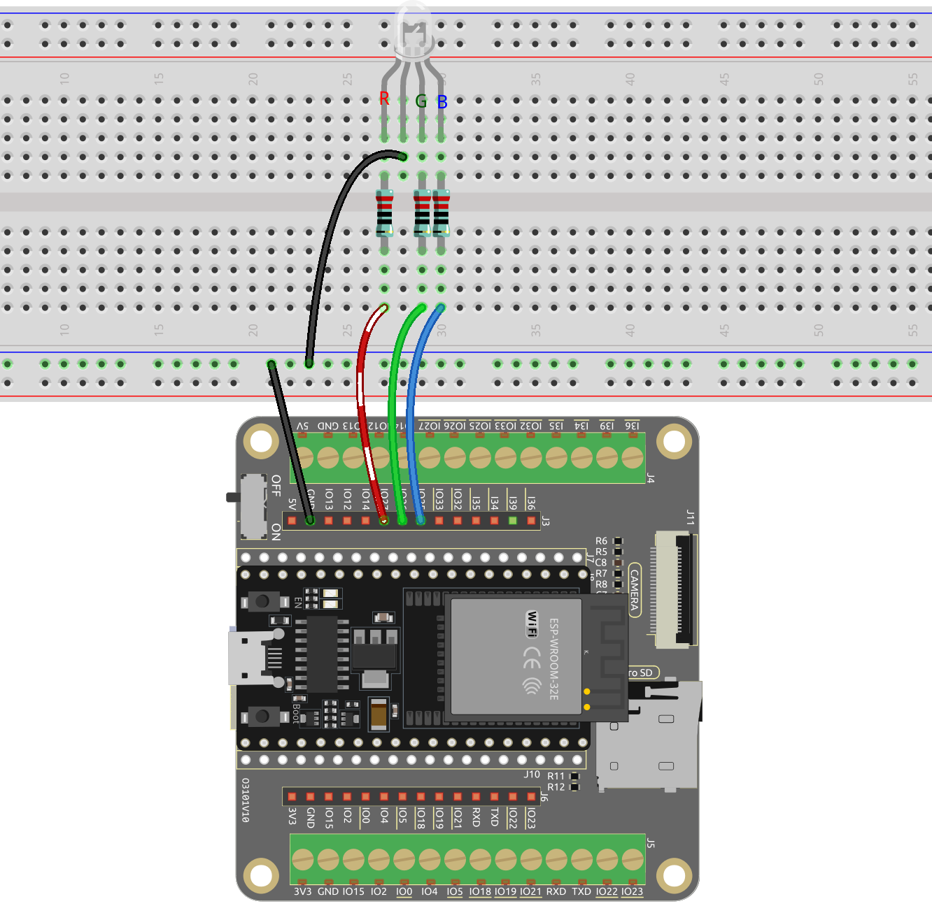
Wiring
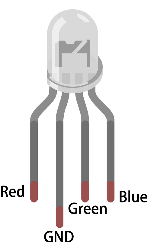
The RGB LED has 4 pins: the long pin is the common cathode pin, which is usually connected to GND; the left pin next to the longest pin is Red; and the two pins on the right are Green and Blue.
Code
Note
Open the
2.3_colorful_light.pyfile located in theesp32-starter-kit-main\micropython\codespath, or copy and paste the code into Thonny. Then, click “Run Current Script” or press F5 to execute it.Make sure to select the “MicroPython (ESP32).COMxx” interpreter in the bottom right corner.
from machine import Pin, PWM
import time

# Define the GPIO pins for the RGB LED
RED_PIN = 27
GREEN_PIN = 26
BLUE_PIN = 25


# Set up the PWM channels
red = PWM(Pin(RED_PIN))
green = PWM(Pin(GREEN_PIN))
blue = PWM(Pin(BLUE_PIN))

# Set the PWM frequency
red.freq(1000)
green.freq(1000)
blue.freq(1000)

def set_color(r, g, b):
    red.duty(r)
    green.duty(g)
    blue.duty(b)

while True:
    # Set different colors and wait for a while
    set_color(1023, 0, 0) # Red
    time.sleep(1)
    set_color(0, 1023, 0) # Green
    time.sleep(1)
    set_color(0, 0, 1023) # Blue
    time.sleep(1)
    set_color(1023, 0, 1023) # purple
    time.sleep(1)
When the script runs, you will see the RGB LEDs display red, green, blue and purple, and so on.
Learn More
You can also set the color you want with the following code with the familiar color values of 0~255.
Note
Open the
2.3_colorful_light_rgb.pyfile located in theesp32-starter-kit-main\micropython\codespath, or copy and paste the code into Thonny. Then, click “Run Current Script” or press F5 to execute it.Make sure to select the “MicroPython (ESP32).COMxx” interpreter in the bottom right corner.
from machine import Pin, PWM
import time

# Define the GPIO pins for the RGB LED
RED_PIN = 27
GREEN_PIN = 26
BLUE_PIN = 25

# Set up the PWM channels
red = PWM(Pin(RED_PIN))
green = PWM(Pin(GREEN_PIN))
blue = PWM(Pin(BLUE_PIN))

# Set the PWM frequency
red.freq(1000)
green.freq(1000)
blue.freq(1000)

# Map input values from one range to another
def interval_mapping(x, in_min, in_max, out_min, out_max):
    return (x - in_min) * (out_max - out_min) / (in_max - in_min) + out_min

# Convert color values (0-255) to duty cycle values (0-1023)
def color_to_duty(rgb_value):
    rgb_value = int(interval_mapping(rgb_value,0,255,0,1023))
    return rgb_value

def set_color(red_value,green_value,blue_value):
    red.duty(color_to_duty(red_value))
    green.duty(color_to_duty(green_value))
    blue.duty(color_to_duty(blue_value))

while True:
    # Set different colors and wait for a while
    set_color(255, 0, 0) # Red
    time.sleep(1)
    set_color(0, 255, 0) # Green
    time.sleep(1)
    set_color(0, 0, 255) # Blue
    time.sleep(1)
    set_color(255, 0, 255) # purple
    time.sleep(1)
This code is based on the previous example, but it maps color values from 0 to 255 to a duty cycle range of 0 to 1023.
The
interval_mappingfunction is a utility function that maps a value from one range to another. It takes five arguments: the input value, the minimum and maximum values of the input range, and the minimum and maximum values of the output range. It returns the input value mapped to the output range.def color_to_duty(rgb_value): rgb_value = int(interval_mapping(rgb_value,0,255,0,1023)) return rgb_value
The
color_to_dutyfunction takes an integer RGB value (e.g. 255,0,255) and maps it to a duty cycle value suitable for the PWM pins. The input RGB value is first mapped from the range 0-255 to the range 0-1023 using theinterval_mappingfunction. The output ofinterval_mappingis then returned as the duty cycle value.def color_to_duty(rgb_value): rgb_value = int(interval_mapping(rgb_value,0,255,0,1023)) return rgb_value
The
color_setfunction takes three integer arguments: the red, green, and blue values for the LED. These values are passed tocolor_to_dutyto obtain the duty cycle values for the PWM pins. The duty cycle values are then set for the corresponding pins using thedutymethod.def set_color(red_value,green_value,blue_value): red.duty(color_to_duty(red_value)) green.duty(color_to_duty(green_value)) blue.duty(color_to_duty(blue_value))