Note
Hello, welcome to the SunFounder Raspberry Pi & Arduino & ESP32 Enthusiasts Community on Facebook! Dive deeper into Raspberry Pi, Arduino, and ESP32 with fellow enthusiasts.
Why Join?
Expert Support: Solve post-sale issues and technical challenges with help from our community and team.
Learn & Share: Exchange tips and tutorials to enhance your skills.
Exclusive Previews: Get early access to new product announcements and sneak peeks.
Special Discounts: Enjoy exclusive discounts on our newest products.
Festive Promotions and Giveaways: Take part in giveaways and holiday promotions.
👉 Ready to explore and create with us? Click [here] and join today!
5.5 Detect Human Movement
Passive infrared sensor (PIR sensor) is a common sensor that can measure infrared (IR) light emitted by objects in its field of view. Simply put, it will receive infrared radiation emitted from the body, thereby detecting the movement of people and other animals. More specifically, it tells the main control board that someone has entered your room.
Required Components
In this project, we need the following components.
It’s definitely convenient to buy a whole kit, here’s the link:
Name |
ITEMS IN THIS KIT |
LINK |
|---|---|---|
ESP32 Starter Kit |
320+ |
You can also buy them separately from the links below.
COMPONENT INTRODUCTION |
PURCHASE LINK |
|---|---|
Available Pins
Available Pins
Here is a list of available pins on the ESP32 board for this project.
For Input
IO13, IO14, IO27, IO26, IO25, IO33, I35, I34, I39, I36, IO4, IO18, IO19, IO21, IO22, IO23
For Output
IO13, IO12, IO14, IO27, IO26, IO25, IO33, IO32, IO15, IO2, IO0, IO4, IO5, IO18, IO19, IO21, IO22, IO23
Note
IO32 cannot be used as input pin in this project because it is internally connected to a 1K pull-down resistor, which sets its default value to 0.
Strapping Pins (Input)
Strapping pins are a special set of pins that are used to determine specific boot modes during device startup (i.e., power-on reset).
Strapping Pins
IO5, IO0, IO2, IO12, IO15
Generally, it is not recommended to use them as input pins. If you wish to use these pins, consider the potential impact on the booting process. For more details, please refer to the Strapping Pins section.
Schematic
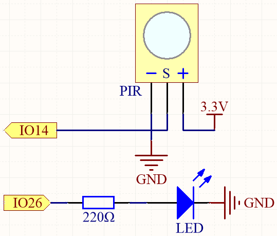
When the PIR module detects motion, IO14 will go high, and the LED will be lit. Otherwise, when no motion is detected, IO14 will be low, and the LED will turn off.
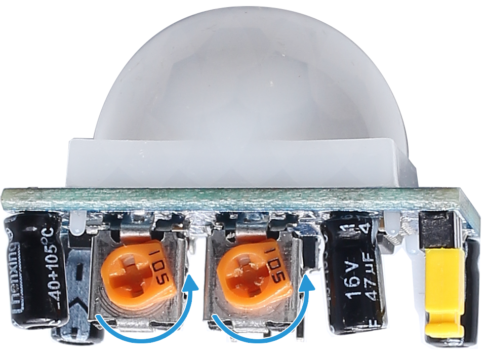
Note
The PIR module has two potentiometers: one adjusts sensitivity, the other adjusts detection distance. To make the PIR module work better, you need to turn both of them counterclockwise to the end.
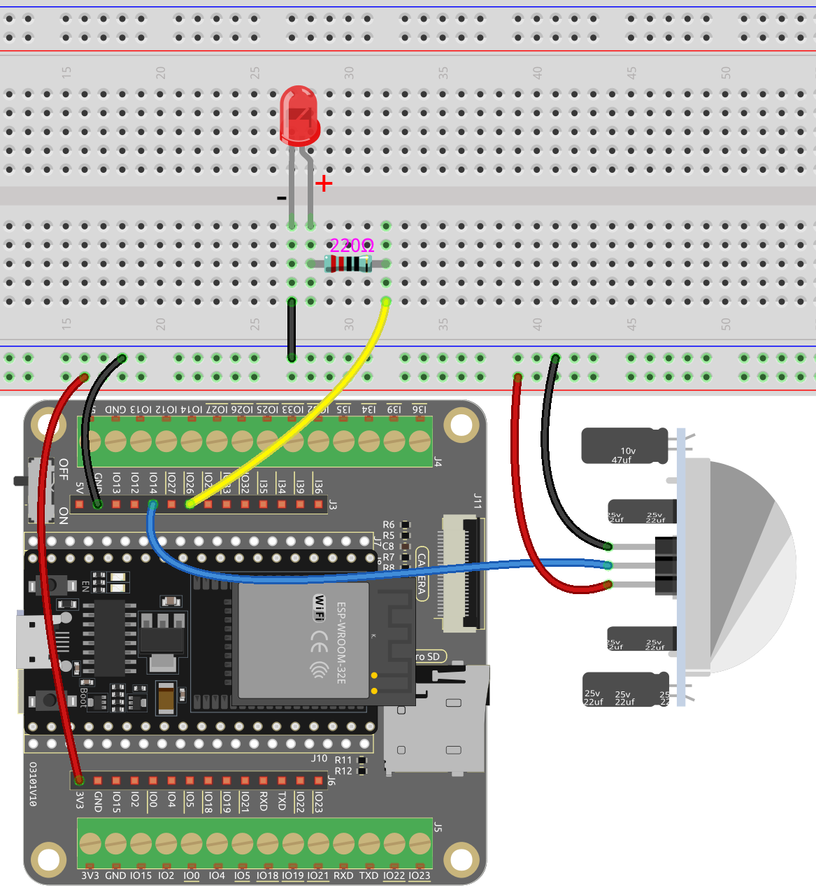
Wiring
Code
Note
Open the
5.5_detect_human_movement.pyfile located in theesp32-starter-kit-main\micropython\codespath, or copy and paste the code into Thonny. Then, click “Run Current Script” or press F5 to execute it.Make sure to select the “MicroPython (ESP32).COMxx” interpreter in the bottom right corner.
import machine
import time

# Define pins
PIR_PIN = 14    # PIR sensor
LED_PIN = 26    # LED

# Initialize the PIR sensor pin as an input pin
pir_sensor = machine.Pin(PIR_PIN, machine.Pin.IN, machine.Pin.PULL_DOWN)
# Initialize the LED pin as an output pin
led = machine.Pin(LED_PIN, machine.Pin.OUT)

# Global flag to indicate motion detected
motion_detected_flag = False

# Function to handle the interrupt
def motion_detected(pin):
    global motion_detected_flag
    print("Motion detected!")
    motion_detected_flag = True

# Attach the interrupt to the PIR sensor pin
pir_sensor.irq(trigger=machine.Pin.IRQ_RISING, handler=motion_detected)

# Main loop
while True:
    if motion_detected_flag:
        led.value(1)  # Turn on the LED
        time.sleep(5)  # Keep the LED on for 5 seconds
        led.value(0)  # Turn off the LED
        motion_detected_flag = False
When the script is running, the LED will light up for 5 seconds and then go off when the PIR module detects someone passing.
Note
The PIR module has two potentiometers: one adjusts sensitivity, the other adjusts detection distance. To make the PIR module work better, you need to turn both of them counterclockwise to the end.
How it work?
This code sets up a simple motion detection system using a PIR sensor and an LED. When motion is detected, the LED will turn on for 5 seconds.
Here’s a breakdown of the code:
Define the interrupt handler function that will be executed when motion is detected:
def motion_detected(pin):
    global motion_detected_flag
    print("Motion detected!")
    motion_detected_flag = True
Attach the interrupt to the PIR sensor pin, with the trigger set to “rising” (i.e., when the pin goes from low to high voltage):
pir_sensor.irq(trigger=machine.Pin.IRQ_RISING, handler=motion_detected)
This sets up an interrupt on the
pir_sensorpin, which is connected to the PIR motion sensor.Here’s a detailed explanation of the parameters:
trigger=machine.Pin.IRQ_RISING: This parameter sets the trigger condition for the interrupt. In this case, the interrupt will be triggered on a rising edge. A rising edge is when the voltage on the pin changes from a low state (0V) to a high state (typically 3.3V or 5V, depending on your hardware). For a PIR motion sensor, when motion is detected, the output pin usually goes from low to high, making the rising edge an appropriate trigger condition.handler=motion_detected: This parameter specifies the function that will be executed when the interrupt is triggered. In this case, themotion_detectedfunction is provided as the interrupt handler. This function will be called automatically when the interrupt condition (rising edge) is detected on thepir_sensorpin.
So, this line of code configures the PIR sensor to call the
motion_detectedfunction whenever motion is detected by the sensor, due to the output pin going from a low to a high state.In the main loop, if the
motion_detected_flagis set toTrue, the LED will be turned on for 5 seconds and then turned off. The flag is then reset toFalseto wait for the next motion event.while True: if motion_detected_flag: led.value(1) # Turn on the LED time.sleep(5) # Keep the LED on for 5 seconds led.value(0) # Turn off the LED motion_detected_flag = False