Note
Hello, welcome to the SunFounder Raspberry Pi & Arduino & ESP32 Enthusiasts Community on Facebook! Dive deeper into Raspberry Pi, Arduino, and ESP32 with fellow enthusiasts.
Why Join?
Expert Support: Solve post-sale issues and technical challenges with help from our community and team.
Learn & Share: Exchange tips and tutorials to enhance your skills.
Exclusive Previews: Get early access to new product announcements and sneak peeks.
Special Discounts: Enjoy exclusive discounts on our newest products.
Festive Promotions and Giveaways: Take part in giveaways and holiday promotions.
👉 Ready to explore and create with us? Click [here] and join today!
5.7 Feel the Light
The photoresistor is a commonly used device for analog inputs, similar to a potentiometer. Its resistance value changes based on the intensity of the light it receives. When exposed to strong light, the resistance of the photoresistor decreases, and as the light intensity decreases, the resistance increases.
By reading the value of the photoresistor, we can gather information about the ambient light conditions. This information can be used for tasks such as controlling the brightness of an LED, adjusting the sensitivity of a sensor, or implementing light-dependent actions in a project.
Required Components
In this project, we need the following components.
It’s definitely convenient to buy a whole kit, here’s the link:
Name |
ITEMS IN THIS KIT |
LINK |
|---|---|---|
ESP32 Starter Kit |
320+ |
You can also buy them separately from the links below.
COMPONENT INTRODUCTION |
PURCHASE LINK |
|---|---|
Available Pins
Available Pins
Here is a list of available pins on the ESP32 board for this project.
Available Pins
IO14, IO25, I35, I34, I39, I36
Strapping Pins
The following pins are strapping pins, which affect the startup process of the ESP32 during power on or reset. However, once the ESP32 is booted up successfully, they can be used as regular pins.
Strapping Pins
IO0, IO12
Schematic
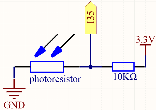
As the light intensity increases, the resistance of the light-dependent resistor (LDR) decreases, resulting in a decrease in the value read on I35.
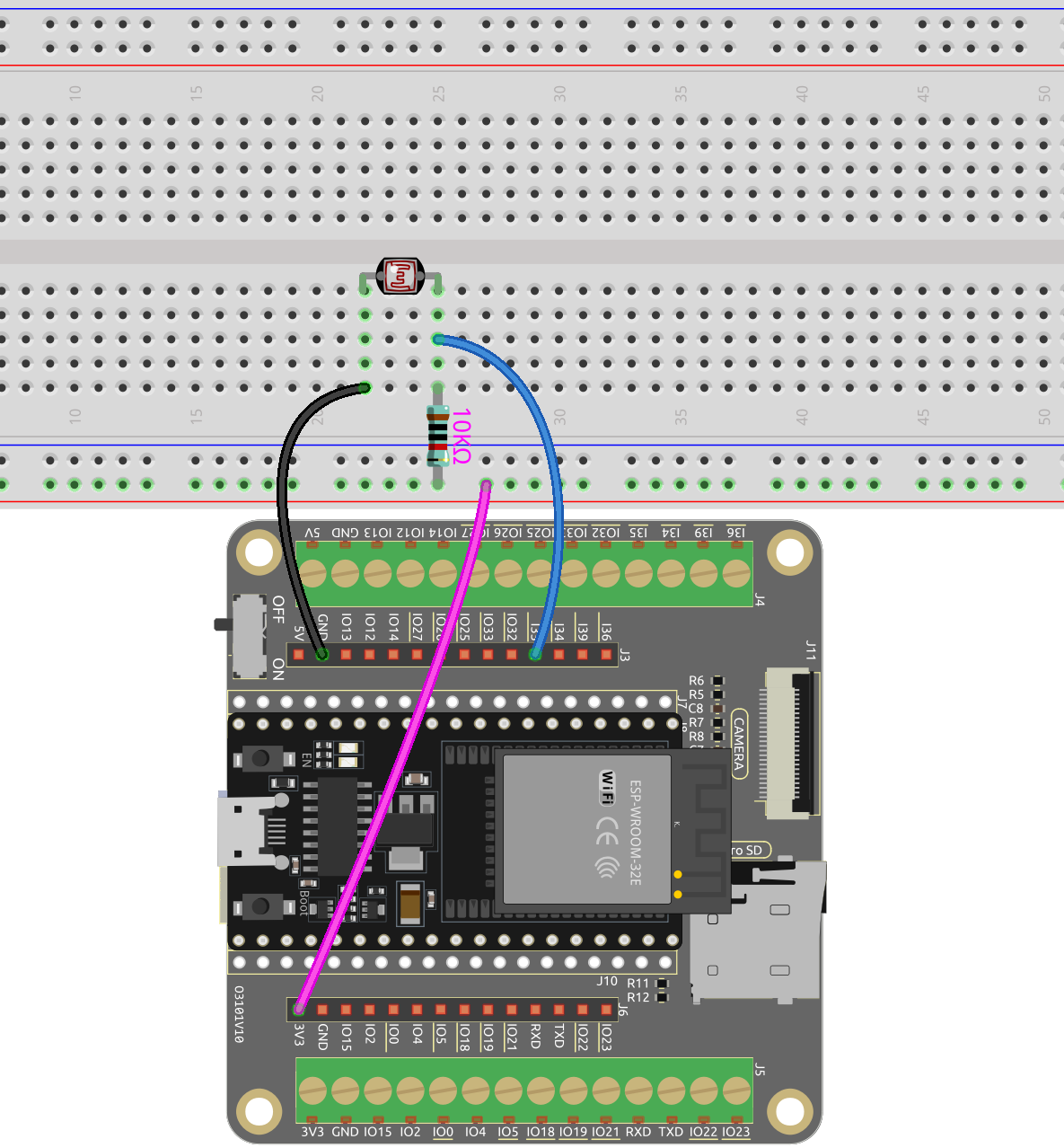
Wiring
Code
Note
Open the
5.7_feel_the_light.pyfile located in theesp32-starter-kit-main\micropython\codespath, or copy and paste the code into Thonny. Then, click “Run Current Script” or press F5 to execute it.Make sure to select the “MicroPython (ESP32).COMxx” interpreter in the bottom right corner.
from machine import ADC,Pin
import time

# create an ADC object acting on a pin
photoresistor = ADC(Pin(35, Pin.IN))

# Configure the ADC attenuation to 11dB for full range
photoresistor.atten(photoresistor.ATTN_11DB)

while True:

    # read a raw analog value in the range 0-4095
    value = photoresistor.read()
    print(value)
    time.sleep(0.05)
After the program runs, the Shell prints out the photoresistor values. You can shine a flashlight on it or cover it up with your hand to see how the value will change.
atten(photoresistor.ATTN_11DB): Configure the ADC attenuation to 11dB for full range.To read voltages above the reference voltage, apply input attenuation with the atten keyword argument.
Valid values (and approximate linear measurement ranges) are:
ADC.ATTN_0DB: No attenuation (100mV - 950mV)
ADC.ATTN_2_5DB: 2.5dB attenuation (100mV - 1250mV)
ADC.ATTN_6DB: 6dB attenuation (150mV - 1750mV)
ADC.ATTN_11DB: 11dB attenuation (150mV - 2450mV)