Note
Hello, welcome to the SunFounder Raspberry Pi & Arduino & ESP32 Enthusiasts Community on Facebook! Dive deeper into Raspberry Pi, Arduino, and ESP32 with fellow enthusiasts.
Why Join?
Expert Support: Solve post-sale issues and technical challenges with help from our community and team.
Learn & Share: Exchange tips and tutorials to enhance your skills.
Exclusive Previews: Get early access to new product announcements and sneak peeks.
Special Discounts: Enjoy exclusive discounts on our newest products.
Festive Promotions and Giveaways: Take part in giveaways and holiday promotions.
👉 Ready to explore and create with us? Click [here] and join today!
5.11 Toggle the Joystick
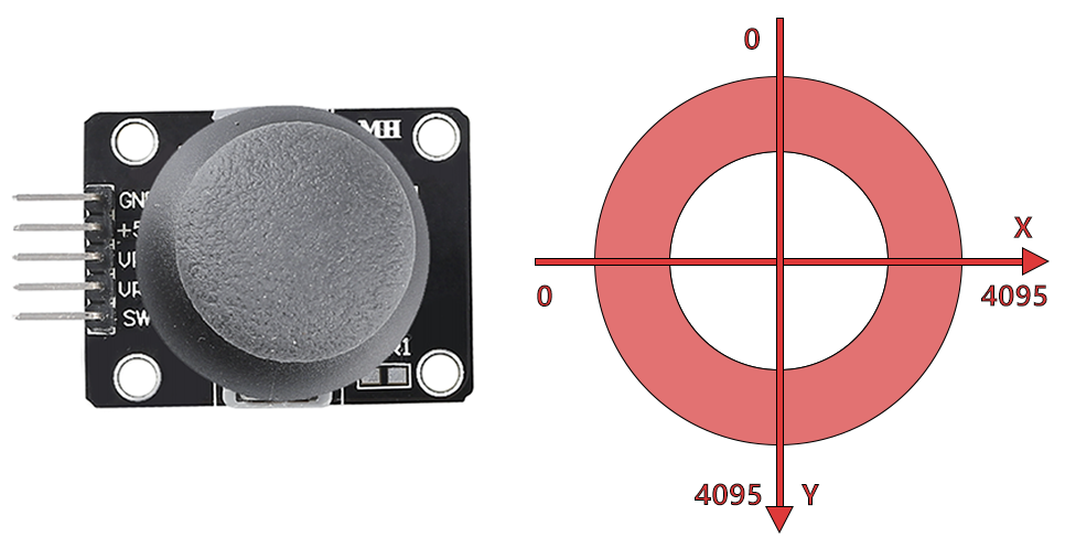
If you play a lot of video games, then you should be very familiar with the Joystick. It is usually used to move the character around, rotate the screen, etc.
The principle behind Joystick’s ability to allow the computer to read our actions is very simple. It can be thought of as consisting of two potentiometers that are perpendicular to each other. These two potentiometers measure the analog value of the joystick vertically and horizontally, resulting in a value (x,y) in a planar right-angle coordinate system.
The joystick of this kit also has a digital input, which is activated when the joystick is pressed.
Required Components
In this project, we need the following components.
It’s definitely convenient to buy a whole kit, here’s the link:
Name |
ITEMS IN THIS KIT |
LINK |
|---|---|---|
ESP32 Starter Kit |
320+ |
You can also buy them separately from the links below.
COMPONENT INTRODUCTION |
PURCHASE LINK |
|---|---|
Available Pins
Here is a list of available pins on the ESP32 board for this project.
For Analog Input
IO14, IO25, I35, I34, I39, I36
For Digital Input
IO13, IO14, IO27, IO26, IO25, IO33, IO4, IO18, IO19, IO21, IO22, IO23
Strapping Pins (Input)
Strapping pins are a special set of pins that are used to determine specific boot modes during device startup (i.e., power-on reset).
Strapping Pins
IO5, IO0, IO2, IO12, IO15
Generally, it is not recommended to use them as input pins. If you wish to use these pins, consider the potential impact on the booting process. For more details, please refer to the Strapping Pins section.
Schematic
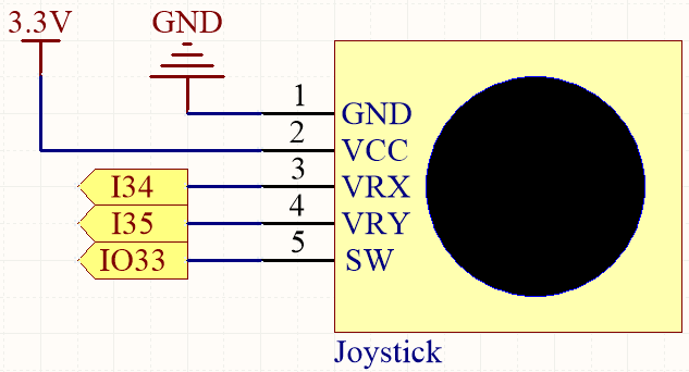
The SW (Z-axis) pin is connected to IO33, which has a built-in 4.7K pull-up resistor. Therefore, when the SW button is not pressed, it will output a high level. When the button is pressed, it will output a low level.
I34 and I35 will change their values as you manipulate the joystick. The range of values is from 0 to 4095.
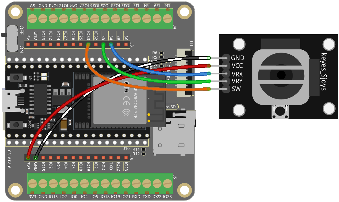
Wiring
Code
Note
Open the
5.11_joystick.pyfile located in theesp32-starter-kit-main\micropython\codespath, or copy and paste the code into Thonny. Then, click “Run Current Script” or press F5 to execute it.Make sure to select the “MicroPython (ESP32).COMxx” interpreter in the bottom right corner.
from machine import ADC,Pin
import time

xAxis = ADC(Pin(34, Pin.IN)) # create an ADC object acting on a pin
xAxis.atten(xAxis.ATTN_11DB)
yAxis = ADC(Pin(35, Pin.IN)) # create an ADC object acting on a pin
yAxis.atten(yAxis.ATTN_11DB)
button = Pin(33, Pin.IN, Pin.PULL_UP)

while True:
    xValue = xAxis.read()  # read a raw analog value in the range 0-4095
    yValue = yAxis.read()  # read a raw analog value in the range 0-4095
    btnValue = button.value()
    print(f"X:{xValue}, Y:{yValue}, Button:{btnValue}")
    time.sleep(0.1)
When the program runs, the Shell prints out the x, y, and button values of joystick.
X:1921, Y:1775, Button:0
X:1921, Y:1775, Button:0
X:1923, Y:1775, Button:0
X:1924, Y:1776, Button:0
X:1926, Y:1777, Button:0
X:1925, Y:1776, Button:0
X:1924, Y:1776, Button:0
The x-axis and y-axis values are analog values that vary from 0 to 4095.
The button is a digital value with a status of 1(release) or 0(press).