Note
Hello, welcome to the SunFounder Raspberry Pi & Arduino & ESP32 Enthusiasts Community on Facebook! Dive deeper into Raspberry Pi, Arduino, and ESP32 with fellow enthusiasts.
Why Join?
Expert Support: Solve post-sale issues and technical challenges with help from our community and team.
Learn & Share: Exchange tips and tutorials to enhance your skills.
Exclusive Previews: Get early access to new product announcements and sneak peeks.
Special Discounts: Enjoy exclusive discounts on our newest products.
Festive Promotions and Giveaways: Take part in giveaways and holiday promotions.
👉 Ready to explore and create with us? Click [here] and join today!
2.1 Hello, LED!
Just as printing “Hello, world!” is the first step in learning to program, using a program to drive an LED is the traditional introduction to learning physical programming.
Required Components
In this project, we need the following components.
It’s definitely convenient to buy a whole kit, here’s the link:
Name |
ITEMS IN THIS KIT |
LINK |
|---|---|---|
ESP32 Starter Kit |
320+ |
You can also buy them separately from the links below.
COMPONENT INTRODUCTION |
PURCHASE LINK |
|---|---|
Available Pins
Here is a list of available pins on the ESP32 board for this project.
Available Pins |
IO13, IO12, IO14, IO27, IO26, IO25, IO33, IO32, IO15, IO2, IO0, IO4, IO5, IO18, IO19, IO21, IO22, IO23 |
Schematic
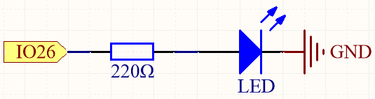
This circuit works on a simple principle, and the current direction is shown in the figure. The LED will light up after the 220ohm current limiting resistor when pin26 outputs high level. The LED will turn off when pin26 outputs low level.
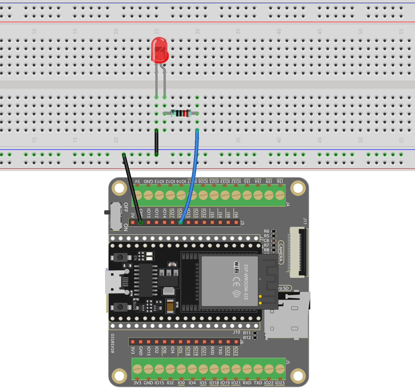
Wiring
Run the Code
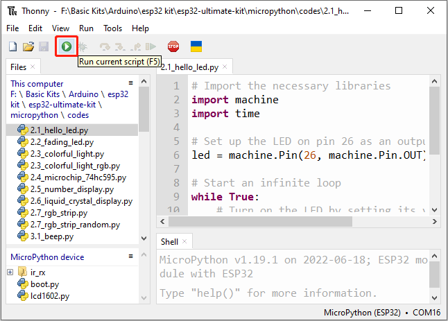
Open the
2.1_hello_led.pyfile located in theesp32-starter-kit-main\micropython\codespath, or copy and paste the code into Thonny.# Import the necessary libraries import machine import time # Set up the LED on pin 26 as an output pin led = machine.Pin(26, machine.Pin.OUT) # Start an infinite loop while True: # Turn on the LED by setting its value to 1 (HIGH) led.value(1) # Wait for 1 second (1000 milliseconds) while the LED is on time.sleep(1) # Turn off the LED by setting its value to 0 (LOW) led.value(0) # Wait for 0.5 seconds (500 milliseconds) while the LED is off time.sleep(0.5)
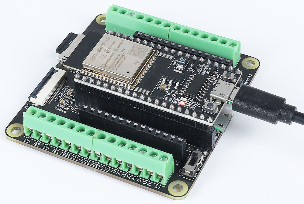
Connect the ESP32 board to your computer using a USB cable.
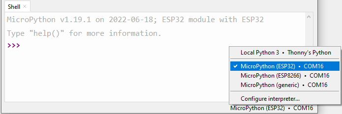
Then click on the “MicroPython (ESP32).COMXX” interpreter in the bottom right corner.
Note
If you don’t see any options other than “Local Python 3”, your ESP32 board may not have been recognized by your computer. In that case, you may need to Manually Install Driver for ESP32.
Finally, click “Run Current Script” or press F5 to execute it.
After the code runs, you will see the LED blinking.
How it works?
It imports two modules,
machineandtime. Themachinemodule provides low-level access to the microcontroller’s hardware, while thetimemodule provides functions for time-related operations.import machine import time
Then set up the pin26 as an output pin using the
machine.Pin()function with themachine.Pin.OUTargument.led = machine.Pin(26, machine.Pin.OUT)
In the
While Trueloop, the LED is turned on for one second by setting the value of the pin26 to 1 usingled.value(1)and then set to 0(led.value(0)) to turn it off for one second, and so on in an infinite loop.while True: # Turn on the LED by setting its value to 1 (HIGH) led.value(1) # Wait for 1 second (1000 milliseconds) while the LED is on time.sleep(1) # Turn off the LED by setting its value to 0 (LOW) led.value(0) # Wait for 0.5 seconds (500 milliseconds) while the LED is off time.sleep(0.5)
Learn More
In this project, we used MicroPython’s machine and time module, we can find more ways to use them here.