Note
Hello, welcome to the SunFounder Raspberry Pi & Arduino & ESP32 Enthusiasts Community on Facebook! Dive deeper into Raspberry Pi, Arduino, and ESP32 with fellow enthusiasts.
Why Join?
Expert Support: Solve post-sale issues and technical challenges with help from our community and team.
Learn & Share: Exchange tips and tutorials to enhance your skills.
Exclusive Previews: Get early access to new product announcements and sneak peeks.
Special Discounts: Enjoy exclusive discounts on our newest products.
Festive Promotions and Giveaways: Take part in giveaways and holiday promotions.
👉 Ready to explore and create with us? Click [here] and join today!
5.1 Reading Button Value
In this interactive project, we’ll venture into the realm of button controls and LED manipulation.
The concept is straightforward yet effective. We’ll be reading the state of a button. When the button is pressed down, it registers a high voltage level, or ‘high state’. This action will then trigger an LED to light up.
Required Components
In this project, we need the following components.
It’s definitely convenient to buy a whole kit, here’s the link:
Name |
ITEMS IN THIS KIT |
LINK |
|---|---|---|
ESP32 Starter Kit |
320+ |
You can also buy them separately from the links below.
COMPONENT INTRODUCTION |
PURCHASE LINK |
|---|---|
Available Pins
Available Pins
Here is a list of available pins on the ESP32 board for this project.
For Input
IO14, IO25, I35, I34, I39, I36, IO18, IO19, IO21, IO22, IO23
For Output
IO13, IO12, IO14, IO27, IO26, IO25, IO33, IO32, IO15, IO2, IO0, IO4, IO5, IO18, IO19, IO21, IO22, IO23
Conditional Usage Pins (Input)
The following pins have built-in pull-up or pull-down resistors, so external resistors are not required when using them as input pins:
Conditional Usage Pins
Description
IO13, IO15, IO2, IO4
Pulling up with a 47K resistor defaults the value to high.
IO27, IO26, IO33
Pulling up with a 4.7K resistor defaults the value to high.
IO32
Pulling down with a 1K resistor defaults the value to low.
Strapping Pins (Input)
Strapping pins are a special set of pins that are used to determine specific boot modes during device startup (i.e., power-on reset).
Strapping Pins
IO5, IO0, IO2, IO12, IO15
Generally, it is not recommended to use them as input pins. If you wish to use these pins, consider the potential impact on the booting process. For more details, please refer to the Strapping Pins section.
Schematic
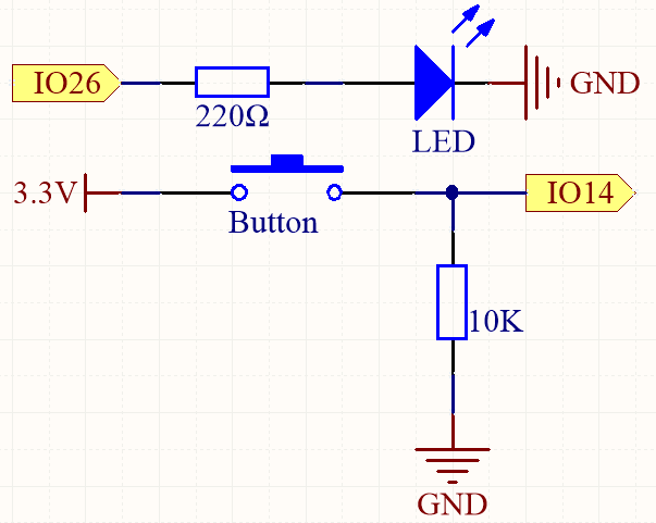
To ensure proper functionality, connect one side of the button pin to 3.3V and the other side to IO14. When the button is pressed, IO14 will be set to high, causing the LED to light up. When the button is released, IO14 will return to its suspended state, which may be either high or low. To ensure a stable low level when the button is not pressed, IO14 should be connected to GND through a 10K pull-down resistor.
Wiring
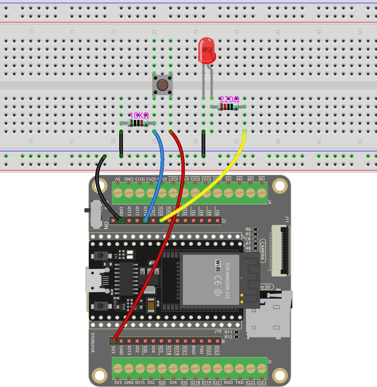
Note
A four-pin button is designed in an H shape. When the button is not pressed, the left and right pins are disconnected, and current cannot flow between them. However, when the button is pressed, the left and right pins are connected, creating a pathway for current to flow.
Code
Note
Open the
5.1_read_button_value.pyfile located in theesp32-starter-kit-main\micropython\codespath, or copy and paste the code into Thonny. Then, click “Run Current Script” or press F5 to execute it.Make sure to select the “MicroPython (ESP32).COMxx” interpreter in the bottom right corner.
import machine
import time

button = machine.Pin(14, machine.Pin.IN) # Button pin
led = machine.Pin(26, machine.Pin.OUT) # LED pin


while True:
    # If the button is pressed by reading its value
    if button.value() == 1:
        # Turn on the LED by setting its value to 1
        led.value(1)
#         time.sleep(0.5)
    else:
        # Turn off the LED
        led.value(0)
During script execution, the LED lights up when you press the button and goes out when you release it.