Note
Hello, welcome to the SunFounder Raspberry Pi & Arduino & ESP32 Enthusiasts Community on Facebook! Dive deeper into Raspberry Pi, Arduino, and ESP32 with fellow enthusiasts.
Why Join?
Expert Support: Solve post-sale issues and technical challenges with help from our community and team.
Learn & Share: Exchange tips and tutorials to enhance your skills.
Exclusive Previews: Get early access to new product announcements and sneak peeks.
Special Discounts: Enjoy exclusive discounts on our newest products.
Festive Promotions and Giveaways: Take part in giveaways and holiday promotions.
👉 Ready to explore and create with us? Click [here] and join today!
7.1 Light Theremin
Theremin is an electronic musical instrument that does not require physical contact. Based on the position of the player’s hand, it produces different tones.
Its controlling section is usually made up of two metal antennas that sense the position of the thereminist’s hands and control oscillators with one hand and volume with the other. The electric signals from the theremin are amplified and sent to a loudspeaker.
We cannot reproduce the same instrument through Pico W, but we can use photoresistor and passive buzzer to achieve similar gameplay.
Required Components
In this project, we need the following components.
It’s definitely convenient to buy a whole kit, here’s the link:
Name |
ITEMS IN THIS KIT |
LINK |
|---|---|---|
Kepler Kit |
450+ |
You can also buy them separately from the links below.
SN |
COMPONENT |
QUANTITY |
LINK |
|---|---|---|---|
1 |
1 |
||
2 |
Micro USB Cable |
1 |
|
3 |
1 |
||
4 |
Several |
||
5 |
1 |
||
6 |
1(S8050) |
||
7 |
3(1KΩ, 220Ω, 10KΩ) |
||
8 |
Passive Buzzer |
1 |
|
9 |
1 |
Schematic
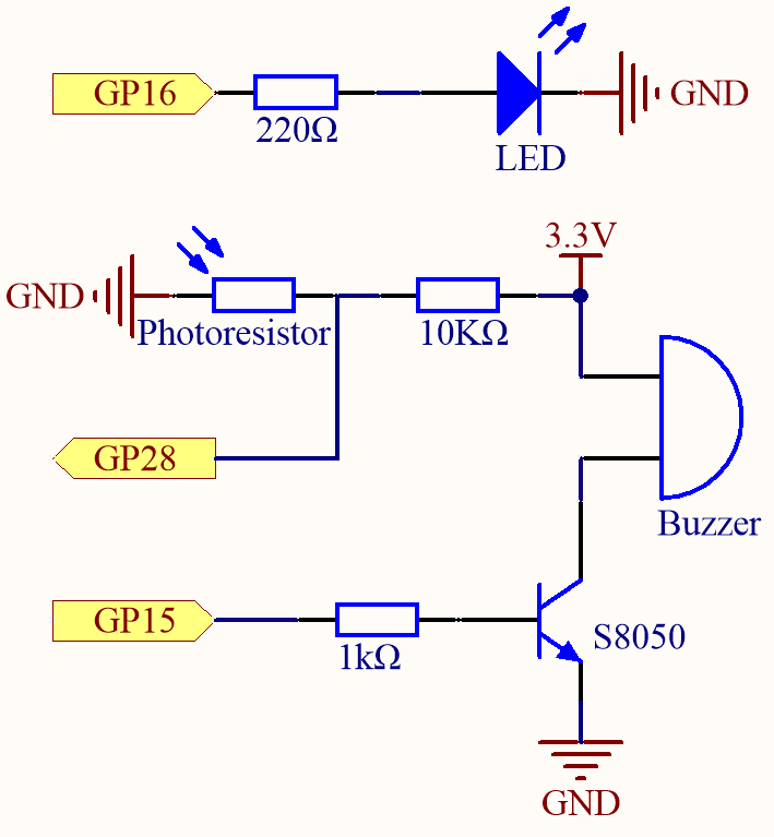
Before starting the project, wave your hand up and down over the photoresistor to calibrate the range of light intensity. The LED connected in GP16 is used to indicate the debugging time, and the LED is lit to indicate the start of debugging and off to indicate the end of debugging.
When GP15 outputs high level, S8050 (NPN transistor) conducts and the passive buzzer starts to sound.
When the light is stronger, GP28’s value is smaller; vice versa, it is larger when the light is weaker. By programming the value of the photoresistor to affect the frequency of the passive buzzer, a photosensitive device can be simulated.
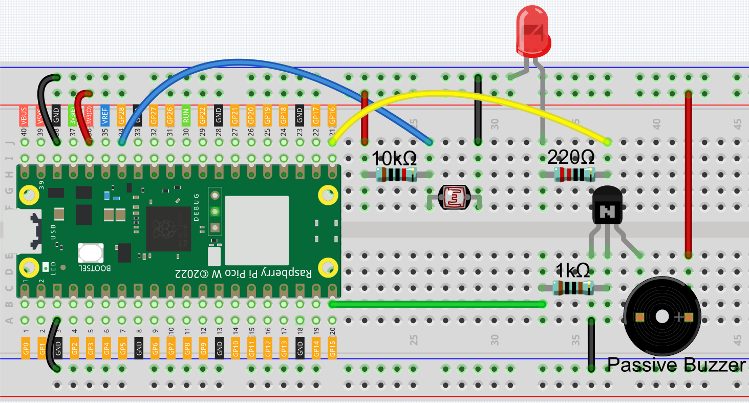
Wiring
Code
Note
Open the
7.1_light_theremin.pyfile under the path ofkepler-kit-main/micropythonor copy this code into Thonny, then click “Run Current Script” or simply press F5 to run it.Don’t forget to click on the “MicroPython (Raspberry Pi Pico)” interpreter in the bottom right corner.
For detailed tutorials, please refer to Open and Run Code Directly.
import machine
import utime

# Initialize LED, photoresistor, and buzzer
led = machine.Pin(16, machine.Pin.OUT)  # LED on pin 16
photoresistor = machine.ADC(28)  # Photoresistor on ADC pin 28
buzzer = machine.PWM(machine.Pin(15))  # Buzzer on pin 15 with PWM

# Variables to store the highest and lowest light readings for calibration
light_low = 65535
light_high = 0

# Function to map one range of values to another
def interval_mapping(x, in_min, in_max, out_min, out_max):
    return (x - in_min) * (out_max - out_min) / (in_max - in_min) + out_min

# Function to play a tone on the buzzer at a specified frequency for a set duration
def tone(pin, frequency, duration):
    pin.freq(frequency)  # Set buzzer frequency
    pin.duty_u16(30000)  # Set duty cycle to around 50%
    utime.sleep_ms(duration)  # Play the tone for the specified duration
    pin.duty_u16(0)  # Turn off the tone by setting duty cycle to 0

# Calibrate the photoresistor by finding the highest and lowest light values over 5 seconds
timer_init_start = utime.ticks_ms()  # Get the current time (start time)
led.value(1)  # Turn on LED to indicate calibration is in progress
while utime.ticks_diff(utime.ticks_ms(), timer_init_start) < 5000:  # Run calibration for 5 seconds
    light_value = photoresistor.read_u16()  # Read the light value from the photoresistor
    if light_value > light_high:  # Track the maximum light value
        light_high = light_value
    if light_value < light_low:  # Track the minimum light value
        light_low = light_value
led.value(0)  # Turn off the LED after calibration

# Main loop to read light levels and play corresponding tones
while True:
    light_value = photoresistor.read_u16()  # Read the current light value from the photoresistor
    pitch = int(interval_mapping(light_value, light_low, light_high, 50, 6000))  # Map light value to a pitch range
    if pitch > 50:  # Only play tones if the pitch is above a minimum threshold
        tone(buzzer, pitch, 20)  # Play the corresponding pitch for 20ms
    utime.sleep_ms(10)  # Small delay between readings
As soon as the program runs, the LED will light up, and we will have five seconds to calibrate the photoresistor’s detection range.
This is due to the different light environments we may have when we use it (e.g., different light intensities at noon and dusk), as well as our hands’ height above the photoresistor. You need to set the maximum and minimum height of your hand from the photoresistor, which is also the height at which you play the instrument.
After five seconds, the LED will turn off, at which point we can wave our hands over the photoresistor and play.