Note
Hello, welcome to the SunFounder Raspberry Pi & Arduino & ESP32 Enthusiasts Community on Facebook! Dive deeper into Raspberry Pi, Arduino, and ESP32 with fellow enthusiasts.
Why Join?
Expert Support: Solve post-sale issues and technical challenges with help from our community and team.
Learn & Share: Exchange tips and tutorials to enhance your skills.
Exclusive Previews: Get early access to new product announcements and sneak peeks.
Special Discounts: Enjoy exclusive discounts on our newest products.
Festive Promotions and Giveaways: Take part in giveaways and holiday promotions.
👉 Ready to explore and create with us? Click [here] and join today!
2.11 Turn the Knob
In the previous projects, we have used the digital input on the Pico W. For example, a button can change the pin from low level (off) to high level (on). This is a binary working state.
However, Pico W can receive another type of input signal: analog input. It can be in any state from fully closed to fully open, and has a range of possible values. The analog input allows the microcontroller to sense the light intensity, sound intensity, temperature, humidity, etc. of the physical world.
Usually, a microcontroller needs an additional hardware to implement analog input-the analogue-to-digital converter (ADC). But Pico W itself has a built-in ADC for us to use directly.
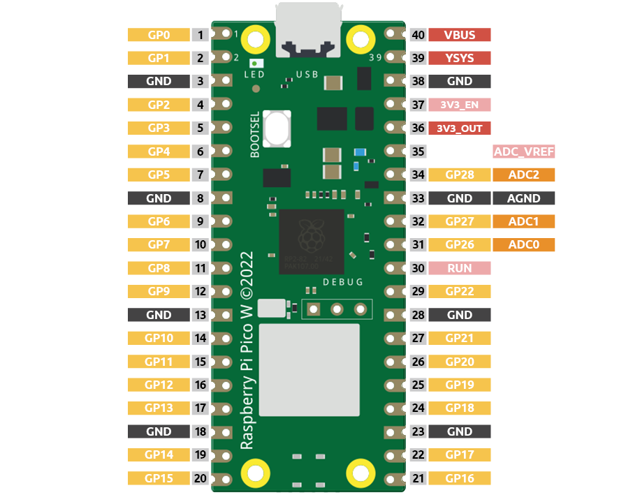
Pico W has three GPIO pins that can use analog input, GP26, GP27, GP28. That is, analog channels 0, 1, and 2. In addition, there is a fourth analog channel, which is connected to the built-in temperature sensor and will not be introduced here.
In this project, we try to read the analog value of potentiometer.
Required Components
In this project, we need the following components.
It’s definitely convenient to buy a whole kit, here’s the link:
Name |
ITEMS IN THIS KIT |
LINK |
|---|---|---|
Kepler Kit |
450+ |
You can also buy them separately from the links below.
SN |
COMPONENT |
QUANTITY |
LINK |
|---|---|---|---|
1 |
1 |
||
2 |
Micro USB Cable |
1 |
|
3 |
1 |
||
4 |
Several |
||
5 |
1(220Ω) |
||
6 |
1 |
||
7 |
1 |
Schematic
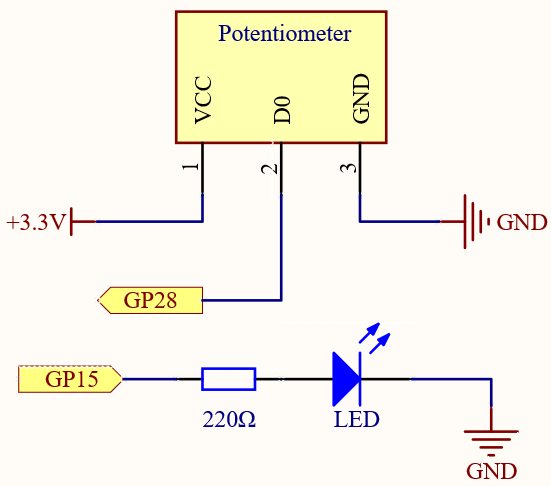
The potentiometer is an analog device and when you turn it in 2 different directions.
Connect the middle pin of the potentiometer to the analog pin GP28. The Raspberry Pi Pico W wcontains a multi-channel, 16-bit analog-to-digital converter. This means that it maps the input voltage between 0 and the operating voltage (3.3V) to an integer value between 0 and 65535, so the GP28 value ranges from 0 to 65535.
The calculation formula is shown below.
(Vp/3.3V) x 65535 = Ap
Then program the value of GP28 (potentiometer) as the PWM value of GP15 (LED). This way you will find that by rotating the potentiometer, the brightness of the LED will change at the same time.
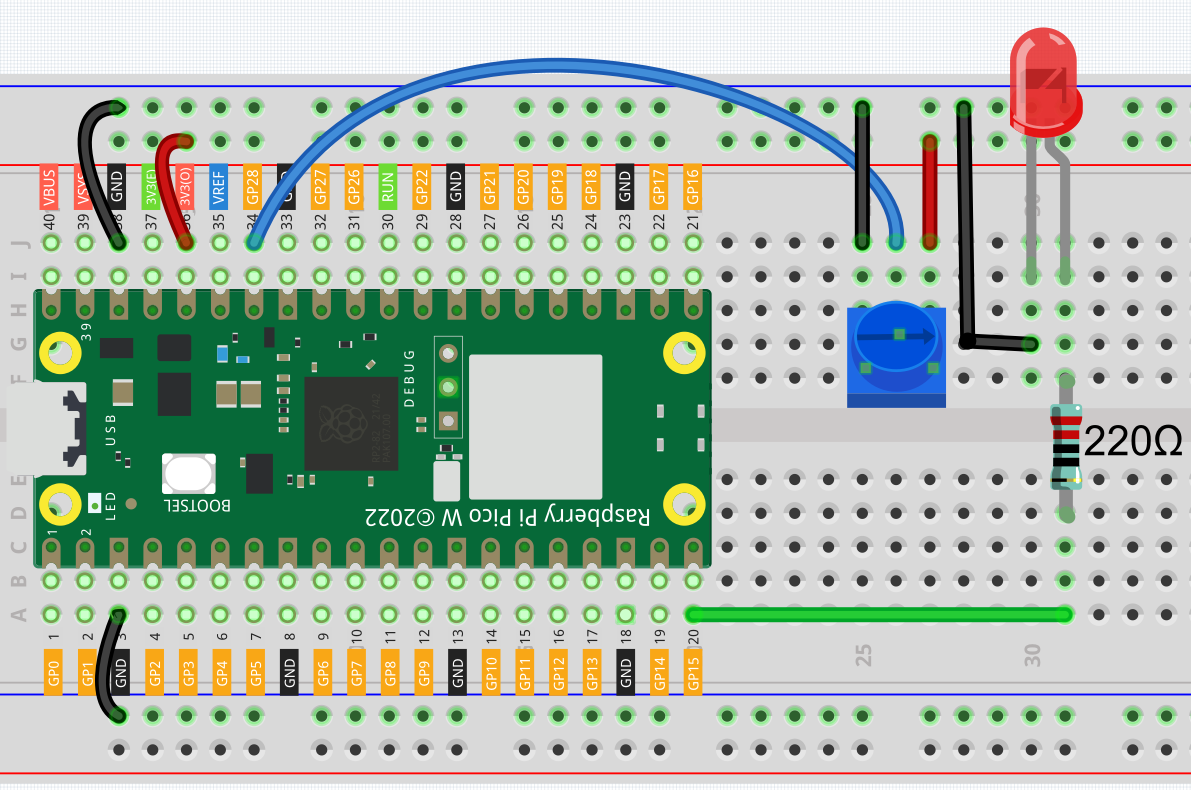
Wiring
Code
Note
Open the
2.11_turn_the_knob.pyfile under the path ofkepler-kit-main/micropythonor copy this code into Thonny, then click “Run Current Script” or simply press F5 to run it.Don’t forget to click on the “MicroPython (Raspberry Pi Pico)” interpreter in the bottom right corner.
For detailed tutorials, please refer to Open and Run Code Directly.
import machine
import utime

potentiometer = machine.ADC(28)
led = machine.PWM(machine.Pin(15))
led.freq(1000)

while True:
    value=potentiometer.read_u16()
    print(value)
    led.duty_u16(value)
    utime.sleep_ms(200)
When the program is running, we can see the analog value currently read by the GP28 pin in the shell. Turn the knob, and the value will change from 0 to 65535. At the same time, the brightness of the LED will increase as the analog value increases.
How it works?
potentiometer = machine.ADC(28)
Access the ADC associated with a source identified by id. In this example it is GP28.
potentiometer.read_u16()
Take an analog reading and return an integer in the range 0-65535. The return value represents the raw reading taken by the ADC, scaled such that the minimum value is 0 and the maximum value is 65535.