6.3 6-axis Motion Tracking
The MPU-6050 is a 6-axis(combines 3-axis Gyroscope, 3-axis Accelerometer) motion tracking devices.
An accelerometer is a tool that measures proper acceleration.For example, an accelerometer at rest on the surface of the Earth will measure an acceleration due to Earth’s gravity, straight upwards[3] (by definition) of g ≈ 9.81 m/s2.
Accelerometers have many uses in industry and science. For example: inertial navigation systems for aircraft and missiles, for keeping images on tablets and digital cameras vertical, etc.
Gyroscopes are used to measure orientation and angular velocity of a device or maintenance. Applications of gyroscopes include anti-rollover and airbag systems for automobiles, motion sensing systems for smart devices, attitude stabilization systems for drones, and more.
Required Components
In this project, we need the following components.
It’s definitely convenient to buy a whole kit, here’s the link:
Name |
ITEMS IN THIS KIT |
LINK |
|---|---|---|
Kepler Kit |
450+ |
You can also buy them separately from the links below.
SN |
COMPONENT |
QUANTITY |
LINK |
|---|---|---|---|
1 |
1 |
||
2 |
Micro USB Cable |
1 |
|
3 |
1 |
||
4 |
Several |
||
5 |
1 |
Schematic
![]()
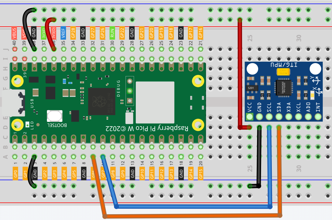
Wiring

Code
Note
Open the
6.3_6axis_motion_tracking.pyfile under the path ofkepler-kit-main/micropythonor copy this code into Thonny, then click “Run Current Script” or simply press F5 to run it.Don’t forget to click on the “MicroPython (Raspberry Pi Pico)” interpreter in the bottom right corner.
For detailed tutorials, please refer to Open and Run Code Directly.
Here you need to use the
imu.pyandvector3d.py, please check if it has been uploaded to Pico W, for a detailed tutorial refer to 1.4 Upload the Libraries to Pico.
from imu import MPU6050
from machine import I2C, Pin
import time

i2c = I2C(1, sda=Pin(6), scl=Pin(7), freq=400000)
mpu = MPU6050(i2c)

while True:
    print("x: %s, y: %s, z: %s"%(mpu.accel.x, mpu.accel.y, mpu.accel.z))
    time.sleep(0.1)
    print("A: %s, B: %s, Y: %s"%(mpu.gyro.x, mpu.gyro.y, mpu.gyro.z))
    time.sleep(0.1)
After running the program, you can see the 3-axis accelerometer values and 3-axis gyroscope values cycling through the output. At this point you rotate the MPU6050 at random, and these values will appear to change accordingly. To make it easier to see the changes, you can comment out one of the print lines and concentrate on another set of data.
The unit of acceleration value is m/s², and the unit of gyroscope value is °/s.
How it works?
In the imu library, we have integrated the relevant functions into the MPU6050 class.
MPU6050 is an I2C module and requires a set of I2C pins to be defined for initialization.
from imu import MPU6050
from machine import I2C, Pin

i2c = I2C(1, sda=Pin(6), scl=Pin(7), freq=400000)
mpu = MPU6050(i2c)
Subsequently, you will be able to get real-time acceleration and angular velocity values in mpu.accel.x, mpu.accel.y, mpu.accel.z, mpu.gyro.x, mpu.gyro.y, mpu.gyro.z.
while True:
    print("x: %s, y: %s, z: %s"%(mpu.accel.x, mpu.accel.y, mpu.accel.z))
    time.sleep(0.1)
    print("A: %s, B: %s, Y: %s"%(mpu.gyro.x, mpu.gyro.y, mpu.gyro.z))
    time.sleep(0.1)