3.7 Swinging Servo
In this kit, in addition to LED and passive buzzer, there is also a device controlled by PWM signal, Servo.
Servo is a position (angle) servo device, which is suitable for those control systems that require constant angle changes and can be maintained. It has been widely used in high-end remote control toys, such as airplanes, submarine models, and remote control robots.
Now, try to make the servo sway!
Required Components
In this project, we need the following components.
It’s definitely convenient to buy a whole kit, here’s the link:
Name |
ITEMS IN THIS KIT |
LINK |
|---|---|---|
Kepler Kit |
450+ |
You can also buy them separately from the links below.
SN |
COMPONENT |
QUANTITY |
LINK |
|---|---|---|---|
1 |
1 |
||
2 |
Micro USB Cable |
1 |
|
3 |
1 |
||
4 |
Several |
||
5 |
1 |
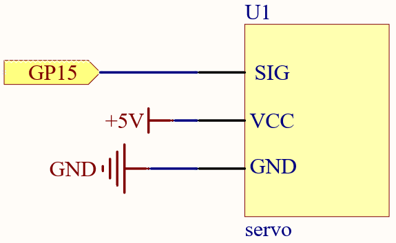
Schematic

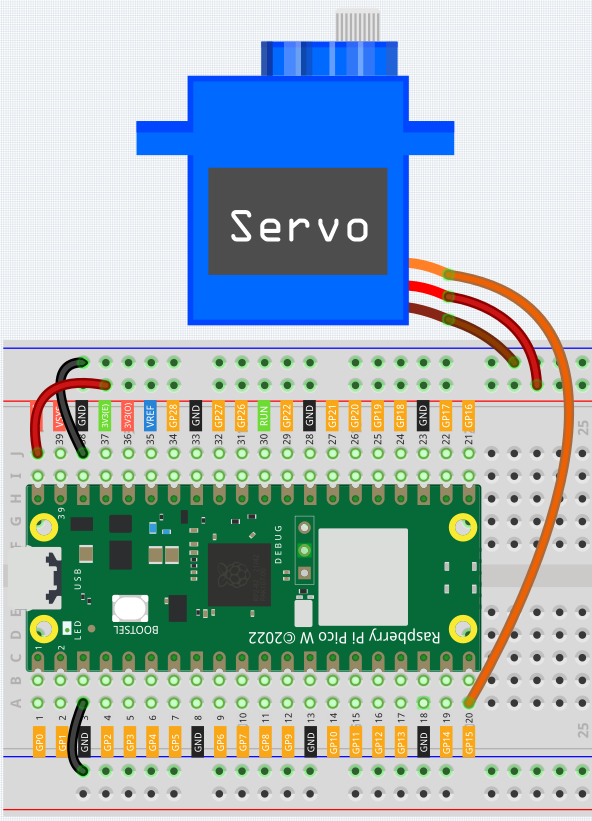
Wiring

Orange wire is signal and connected to GP15.
Red wire is VCC and connected to VBUS(5V).
Brown wire is GND and connected to GND.
Code
Note
Open the
3.7_swinging_servo.pyfile under the path ofkepler-kit-main/micropythonor copy this code into Thonny, then click “Run Current Script” or simply press F5 to run it.Don’t forget to click on the “MicroPython (Raspberry Pi Pico)” interpreter in the bottom right corner.
For detailed tutorials, please refer to Open and Run Code Directly.
import machine
import utime

servo = machine.PWM(machine.Pin(15))
servo.freq(50)

def interval_mapping(x, in_min, in_max, out_min, out_max):
    return (x - in_min) * (out_max - out_min) / (in_max - in_min) + out_min

def servo_write(pin,angle):
    pulse_width=interval_mapping(angle, 0, 180, 0.5,2.5)
    duty=int(interval_mapping(pulse_width, 0, 20, 0,65535))
    pin.duty_u16(duty)

while True:
    for angle in range(180):
        servo_write(servo,angle)
        utime.sleep_ms(20)
    for angle in range(180,-1,-1):
        servo_write(servo,angle)
        utime.sleep_ms(20)
When the program is running, we can see the Servo Arm swinging back and forth from 0° to 180°.
The program will always run because of the while True loop, we need to press the Stop button to end the program.
How it works?
We defined the servo_write() function to make the servo run.
This function has two parameters:
pin, the GPIO pin that controls the servo.Angle, the angle of the shaft output.
In this function, interval_mapping() is called to map the angle range 0 ~ 180 to the pulse width range 0.5 ~ 2.5ms.
pulse_width=interval_mapping(angle, 0, 180, 0.5,2.5)
Why is it 0.5~2.5? This is determined by the working mode of the Servo.
Next, convert the pulse width from period to duty. Since duty_u16() cannot have decimals when used (the value cannot be a float type), we used int() to force the duty to be converted to an int type.
duty=int(interval_mapping(pulse_width, 0, 20, 0,65535))
Finally, write the duty value into duty_u16().