Note
Hello, welcome to the SunFounder Raspberry Pi & Arduino & ESP32 Enthusiasts Community on Facebook! Dive deeper into Raspberry Pi, Arduino, and ESP32 with fellow enthusiasts.
Why Join?
Expert Support: Solve post-sale issues and technical challenges with help from our community and team.
Learn & Share: Exchange tips and tutorials to enhance your skills.
Exclusive Previews: Get early access to new product announcements and sneak peeks.
Special Discounts: Enjoy exclusive discounts on our newest products.
Festive Promotions and Giveaways: Take part in giveaways and holiday promotions.
👉 Ready to explore and create with us? Click [here] and join today!
7.12 Digital Bubble Level
A bubble Level, is an instrument designed to indicate whether a surface is horizontal (level) or vertical (plumb). There are different types of spirit levels used by carpenters, stonemasons, bricklayers, other building trades workers, surveyors, millwrights, and other metalworkers, as well as in some photographic and videographic work.
Here we make a digital bubble level using MPU6050 and 8x8 LED matrix. When you deflect the MPU6050, the bubble on the LED matrix will also be deflected.
Required Components
In this project, we need the following components.
It’s definitely convenient to buy a whole kit, here’s the link:
Name |
ITEMS IN THIS KIT |
LINK |
|---|---|---|
Kepler Kit |
450+ |
You can also buy them separately from the links below.
SN |
COMPONENT |
QUANTITY |
LINK |
|---|---|---|---|
1 |
1 |
||
2 |
Micro USB Cable |
1 |
|
3 |
1 |
||
4 |
Several |
||
5 |
1 |
||
6 |
2 |
||
7 |
1 |
Schematic
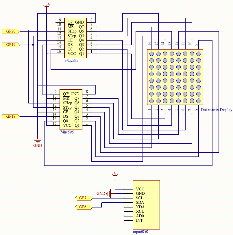
The MPU6050 takes the acceleration values in each direction and calculates the attitude angle.
As a result, the program draws a 2x2 dot on the dot matrix based on data from the two 74HC595 chips.
As the attitude angle changes, the program sends different data to the 74HC595 chips, and the position of the dot changes, creating a bubble effect.
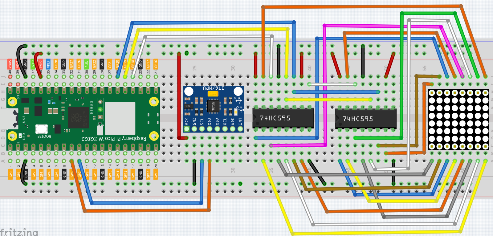
Wiring
Code
Note
Open the
7.12_digital_bubble_level.pyfile under the path ofkepler-kit-main/micropythonor copy this code into Thonny, then click “Run Current Script” or simply press F5 to run it.Don’t forget to click on the “MicroPython (Raspberry Pi Pico)” interpreter in the bottom right corner.
For detailed tutorials, please refer to Open and Run Code Directly.
Here you need to use the
imu.pyandvector3d.py, please check if it has been uploaded to Pico W, for a detailed tutorial refer to 1.4 Upload the Libraries to Pico.
import machine
from machine import I2C, Pin
import time
import math
from imu import MPU6050

# Initialize I2C communication with MPU6050 sensor
i2c = I2C(1, sda=Pin(6), scl=Pin(7), freq=400000)
mpu = MPU6050(i2c)

# Function to calculate the distance between two points
def dist(a, b):
    return math.sqrt((a * a) + (b * b))

# Function to calculate rotation along the y-axis
def get_y_rotation(x, y, z):
    radians = math.atan2(x, dist(y, z))
    return -math.degrees(radians)

# Function to calculate rotation along the x-axis
def get_x_rotation(x, y, z):
    radians = math.atan2(y, dist(x, z))
    return math.degrees(radians)

# Function to get the current angles from the MPU6050 sensor
def get_angle():
    y_angle = get_y_rotation(mpu.accel.x, mpu.accel.y, mpu.accel.z)
    x_angle = get_x_rotation(mpu.accel.x, mpu.accel.y, mpu.accel.z)
    return x_angle, y_angle

# Initialize shift register pins for controlling the LED matrix
sdi = machine.Pin(18, machine.Pin.OUT)
rclk = machine.Pin(19, machine.Pin.OUT)
srclk = machine.Pin(20, machine.Pin.OUT)

# Function to shift data into the shift register
def hc595_in(dat):
    for bit in range(7, -1, -1):
        srclk.low()
        time.sleep_us(30)
        sdi.value(1 & (dat >> bit))
        time.sleep_us(30)
        srclk.high()

# Function to output the data from the shift register to the LED matrix
def hc595_out():
    rclk.high()
    time.sleep_us(200)
    rclk.low()

# Function to display a glyph (8x8 matrix) on the LED matrix
def display(glyph):
    for i in range(0, 8):
        hc595_in(glyph[i])
        hc595_in(0x80 >> i)
        hc595_out()

# Convert a 2D matrix to a glyph that can be displayed on the LED matrix
def matrix_2_glyph(matrix):
    glyph = [0 for i in range(8)]
    for i in range(8):
        for j in range(8):
            glyph[i] += matrix[i][j] << j
    return glyph

# Clamp a value between a specified minimum and maximum
def clamp_number(val, min_val, max_val):
    return min_val if val < min_val else max_val if val > max_val else val

# Map a value from one range to another
def interval_mapping(x, in_min, in_max, out_min, out_max):
    return (x - in_min) * (out_max - out_min) / (in_max - in_min) + out_min

# Calculate the position of the bubble in the matrix based on the MPU6050 readings
sensitivity = 4  # Sensitivity of the bubble movement
matrix_range = 7  # The matrix size is 8x8, so the range is 0-7
point_range = matrix_range - 1  # Bubble's position should be between 0 and 6

# Function to calculate the position of the bubble based on sensor data
def bubble_position():
    y, x = get_angle()  # Get the current rotation angles
    x = int(clamp_number(interval_mapping(x, 90, -90, 0 - sensitivity, point_range + sensitivity), 0, point_range))
    y = int(clamp_number(interval_mapping(y, -90, 90, point_range + sensitivity, 0 - sensitivity), 0, point_range))
    return [x, y]

# Drop the bubble (represented by turning off 2x2 LEDs) into the matrix
def drop_bubble(matrix, bubble):
    matrix[bubble[0]][bubble[1]] = 0
    matrix[bubble[0] + 1][bubble[1]] = 0
    matrix[bubble[0]][bubble[1] + 1] = 0
    matrix[bubble[0] + 1][bubble[1] + 1] = 0
    return matrix

# Main loop
while True:
    matrix = [[1 for i in range(8)] for j in range(8)]  # Create an empty matrix (all LEDs on)
    bubble = bubble_position()  # Get the current bubble position based on sensor data
    matrix = drop_bubble(matrix, bubble)  # Drop the bubble into the matrix
    display(matrix_2_glyph(matrix))  # Display the matrix on the LED grid
    time.sleep(0.1)  # Add a small delay to slow down updates
Once you have run the program, place the breadboard on a level surface. A dot will appear in the center of the LED matrix (if it isn’t in the center, the MPU6050 may not be level). When you deflect the breadboard, the dot will move in the direction you deflected.