Mini Piano
Note
🌟 Welcome to the SunFounder Facebook Community! Whether you’re into Raspberry Pi, Arduino, or ESP32, you’ll find inspiration, help ideas here.
✅ Be the first to get free learning resources.
✅ Stay updated on new products & exclusive giveaways.
✅ Share your creations and get real feedback.
Kit purchase
Looking for parts? Check out our all-in-one kits below — packed with components, beginner-friendly guides, and tons of fun.

Name |
Includes ESP32 board |
PURCHASE LINK |
|---|---|---|
ESP32 Ultimate Starter Kit |
ESP32 WROOM 32E + |
|
Universal Maker Sensor Kit |
Course Introduction
In this lesson, you’ll learn how to create a mini piano using LEDs, buttons, and a passive buzzer with ESP32.
Pressing different buttons will light up the corresponding LED and play the matching pitch on the buzzer.
Note
If this is your first time working with an ESP32 project, we recommend downloading and reviewing the basic materials first.
Required Components
In this project, we need the following components:
SN |
COMPONENT INTRODUCTION |
QUANTITY |
PURCHASE LINK |
|---|---|---|---|
1 |
ESP-WROOM-32 ESP32 ESP-32S Development Board |
1 |
|
2 |
USB Type-C cable |
1 |
|
3 |
Breadboard |
1 |
|
4 |
Wires |
Several |
|
5 |
1kΩ resistor |
Several |
|
6 |
Button |
3 |
|
7 |
LED |
Several |
|
8 |
Passive buzzer |
1 |
Wiring
Common Connections:
LED
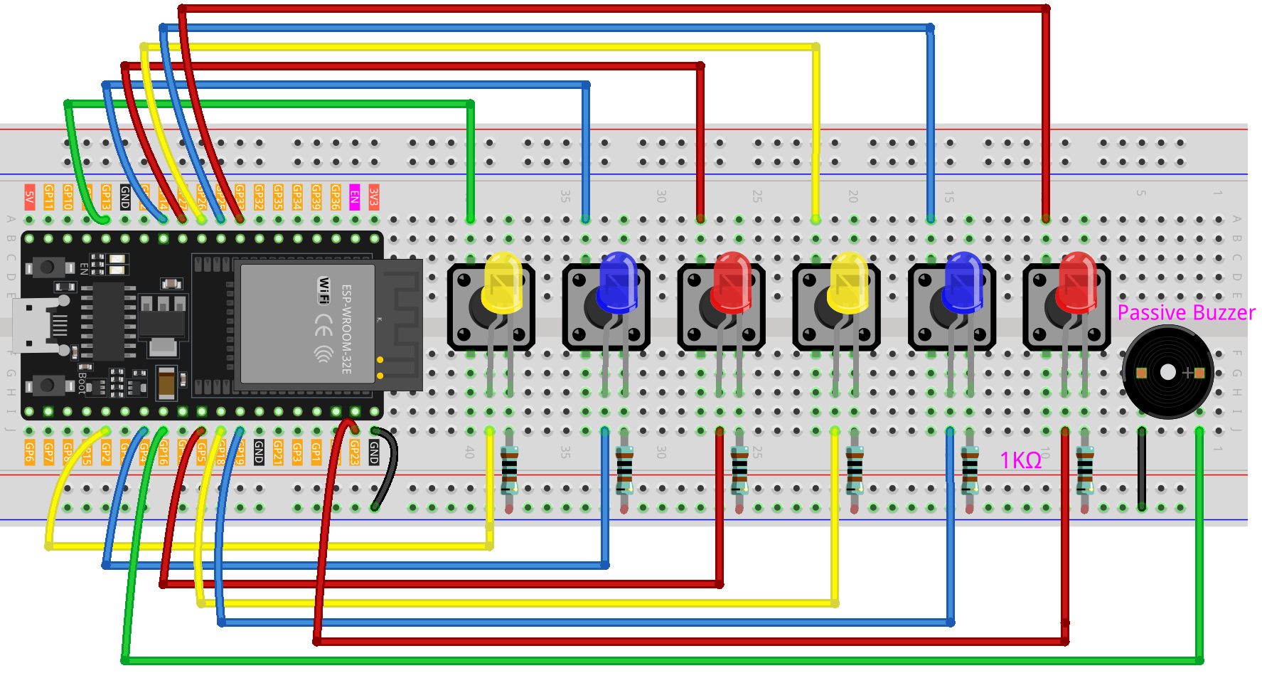
Connect the LEDs cathode to a 1kΩ resistor then to the negative power bus on the breadboard, and the LEDs anode to GPIO2, GPIO4, GPIO5, GPIO18, GPIO19, GPIO23 on the ESP32.
Button
Connect to the LED’s cathode on the breadboard, then connect a 1kΩ resistor from the LED’s negative terminal to the negative power bus on the breadboard.
Connect to GPIO13, GPIO14, GPIO27, GPIO26, GPIO25, GPIO33 on the ESP32.
Passive Buzzer
+: Connect to GPIO16 on the ESP32.
-: Connect to breadboard’s negative power bus.
Writing the Code
Note
Before you begin, you need to upload the pitches.h library to your Arduino. Copy the contents of the library into the Arduino IDE, save it as pitches.h and then upload it to your ESP32.
#include <Arduino.h>
#include <driver/ledc.h>   // Use ESP-IDF LEDC APIs (works across Arduino-ESP32 versions)
#include "pitches.h"

// ---------------- ESP32 Pin Map (safe choices) ----------------
// LEDs for notes C, D, E, F, G, A  (6 LEDs)
const int ledPins[6] = {2, 4, 5, 18, 19, 23};

// Buttons for notes C, D, E, F, G, A  (6 buttons, INPUT_PULLUP)
const int buttonPins[6] = {13, 14, 27, 26, 25, 33};

// Passive buzzer pin (PWM capable)
const int buzzerPin = 16;

// Note frequencies (C4 to A4)
const int noteFrequencies[6] = {
  NOTE_C4, NOTE_D4, NOTE_E4,
  NOTE_F4, NOTE_G4, NOTE_A4
};

// Length of each note in milliseconds
const int noteDuration = 250;

// Pause time between notes
const int pauseDuration = 30;

// ---------------- LEDC (ESP-IDF) config ----------------
static const ledc_timer_t   TONE_TIMER   = LEDC_TIMER_0;
static const ledc_channel_t TONE_CHANNEL = LEDC_CHANNEL_0;
static const ledc_mode_t    TONE_MODE    = LEDC_LOW_SPEED_MODE;  // safe for most pins
static const ledc_timer_bit_t TONE_RES   = LEDC_TIMER_10_BIT;    // 10-bit resolution (0..1023)
static const uint32_t       TONE_DUTY_ON = 512;                  // ~50% duty at 10-bit

// Initialize LEDC once (called in setup)
void initToneLEDC(uint8_t gpioPin) {
  // Timer configuration (base frequency is placeholder; will be changed per note)
  ledc_timer_config_t tcfg = {};
  tcfg.speed_mode       = TONE_MODE;
  tcfg.timer_num        = TONE_TIMER;
  tcfg.duty_resolution  = TONE_RES;
  tcfg.freq_hz          = 1000; // placeholder
  tcfg.clk_cfg          = LEDC_AUTO_CLK;
  ledc_timer_config(&tcfg);

  // Channel configuration
  ledc_channel_config_t ccfg = {};
  ccfg.gpio_num       = gpioPin;
  ccfg.speed_mode     = TONE_MODE;
  ccfg.channel        = TONE_CHANNEL;
  ccfg.intr_type      = LEDC_INTR_DISABLE;
  ccfg.timer_sel      = TONE_TIMER;
  ccfg.duty           = 0;      // start silent
  ccfg.hpoint         = 0;
  ledc_channel_config(&ccfg);
}

// Start tone on pin with given frequency for given duration (ms)
// If duration == 0, the tone keeps playing until noToneESP32() is called.
void toneESP32(int /*pin*/, unsigned int frequency, unsigned long duration = 0) {
  // Set frequency on the configured timer
  ledc_set_freq(TONE_MODE, TONE_TIMER, frequency);
  // Enable output with ~50% duty
  ledc_set_duty(TONE_MODE, TONE_CHANNEL, TONE_DUTY_ON);
  ledc_update_duty(TONE_MODE, TONE_CHANNEL);

  if (duration > 0) {
    delay(duration);
    // Stop after duration
    ledc_set_duty(TONE_MODE, TONE_CHANNEL, 0);
    ledc_update_duty(TONE_MODE, TONE_CHANNEL);
  }
}

void noToneESP32(int /*pin*/) {
  ledc_set_duty(TONE_MODE, TONE_CHANNEL, 0);
  ledc_update_duty(TONE_MODE, TONE_CHANNEL);
}

// ---------------- Arduino sketch logic ----------------
void setup() {
  // LEDs
  for (int i = 0; i < 6; i++) {
    pinMode(ledPins[i], OUTPUT);
    digitalWrite(ledPins[i], LOW);
  }

  // Buttons with internal pull-ups
  for (int i = 0; i < 6; i++) {
    pinMode(buttonPins[i], INPUT_PULLUP);
  }

  pinMode(buzzerPin, OUTPUT);

  // Initialize LEDC tone on the buzzer pin
  initToneLEDC(buzzerPin);

  Serial.begin(115200);
}

void loop() {
  // Scan buttons
  for (int i = 0; i < 6; i++) {
    // Pressed when reads LOW (wired to GND)
    if (digitalRead(buttonPins[i]) == LOW) {
      playNote(i);
      delay(150); // simple debounce
    }
  }
}

// Play a note and flash the matching LED
void playNote(int index) {
  digitalWrite(ledPins[index], HIGH);                 // LED on
  toneESP32(buzzerPin, noteFrequencies[index], noteDuration);
  digitalWrite(ledPins[index], LOW);                  // LED off
  noToneESP32(buzzerPin);                             // ensure stop
  delay(pauseDuration);
}