Joystick LED
Note
🌟 Welcome to the SunFounder Facebook Community! Whether you’re into Raspberry Pi, Arduino, or ESP32, you’ll find inspiration, help ideas here.
✅ Be the first to get free learning resources.
✅ Stay updated on new products & exclusive giveaways.
✅ Share your creations and get real feedback.
Kit purchase
Looking for parts? Check out our all-in-one kits below — packed with components, beginner-friendly guides, and tons of fun.
Name |
Includes ESP32 board |
PURCHASE LINK |
|---|---|---|
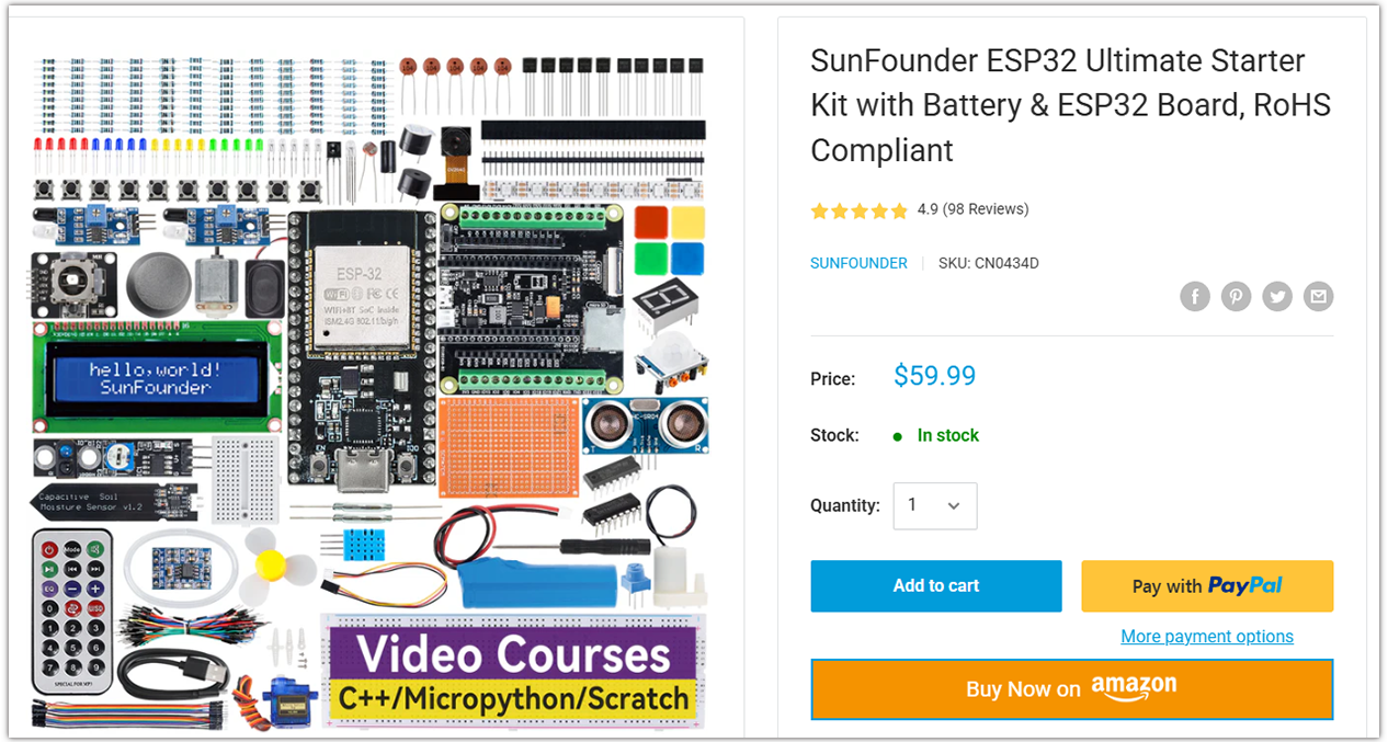
ESP32 Ultimate Starter Kit |
ESP32 WROOM 32E + |
|
Universal Maker Sensor Kit |
Course Introduction
In this lesson, you will learn how to use ESP32 along with Joystick Module, LEDs, and resistors to create a light play.
Note
If this is your first time working with an ESP32 project, we recommend downloading and reviewing the basic materials first.
Required Components
In this project, we need the following components:
SN |
COMPONENT INTRODUCTION |
QUANTITY |
PURCHASE LINK |
|---|---|---|---|
1 |
ESP-WROOM-32 ESP32 ESP-32S Development Board |
1 |
|
2 |
USB Type-C cable |
1 |
|
3 |
Breadboard |
1 |
|
4 |
Wires |
Several |
|
5 |
1kΩ resistor |
Several |
|
6 |
LED |
Several |
|
6 |
Joystick Module |
1 |
Wiring
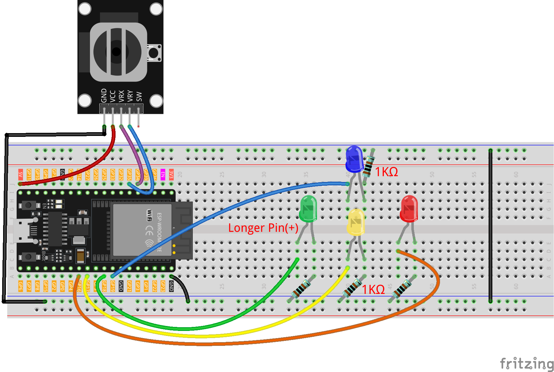
Common Connections:
LED
Blue: Connect the LED anode to GPIO19 on the ESP32, and the cathode to a 1kΩ resistor, then to the negative power bus on the breadboard.
Green: Connect the LED anode to GPIO18 on the ESP32, and the cathode to a 1kΩ resistor, then to the negative power bus on the breadboard.
Yellow: Connect the LED anode to GPIO17**on the ESP32 , and the **cathode to a 1kΩ resistor, then to the negative power bus on the breadboard.
Red: Connect the LED anode to GPIO16 on the ESP32, and the cathode to a 1kΩ resistor, then to the negative power bus on the breadboard.
Joystick Module
VRY: Connect to GPIO35 on the ESP32.
VRX: Connect to GPIO34 on the ESP32.
GND: Connect to breadboard’s negative power bus.
VCC: Connect to breadboard’s red power bus.
Writing the Code
Note
You can copy this code into Arduino IDE.
Don’t forget to select the board(ESP32 Dev module) and the correct port before clicking the Upload button.
// ===== LED pin definitions (ESP32 safe GPIOs) =====
// Avoid strapping pins like 0/2/12/15 for reliability.
// You can change these if they clash with other hardware.
const int redLED    = 16; // negative X (LEFT)
const int yellowLED = 17; // negative Y (DOWN)
const int greenLED  = 18; // positive X (RIGHT)
const int blueLED   = 19; // positive Y (UP)

// ===== Joystick analog inputs (ESP32 ADC1, input-only) =====
// Most joystick modules output 0–3.3V when powered from 3.3V.
// GPIO34/35 are input-only and support analogRead on ADC1.
const int xPin = 34;  // VRX -> GPIO34 (ADC1)
const int yPin = 35;  // VRY -> GPIO35 (ADC1)

// ===== Analog range and dead zone (ESP32 is 12-bit: 0..4095) =====
const int MID_VAL   = 2048; // midpoint for 12-bit ADC
const int DEAD_ZONE = 300;  // adjust as needed

void setup() {
  pinMode(redLED, OUTPUT);
  pinMode(yellowLED, OUTPUT);
  pinMode(greenLED, OUTPUT);
  pinMode(blueLED, OUTPUT);

  // Initialize all LEDs OFF
  digitalWrite(redLED, LOW);
  digitalWrite(yellowLED, LOW);
  digitalWrite(greenLED, LOW);
  digitalWrite(blueLED, LOW);

  Serial.begin(115200);
}

void loop() {
  // Read joystick (ESP32 returns 0..4095 by default)
  int xVal = analogRead(xPin);
  int yVal = analogRead(yPin);

  Serial.print("X: "); Serial.print(xVal);
  Serial.print("  Y: "); Serial.println(yVal);

  // Turn all LEDs OFF before deciding direction
  digitalWrite(redLED, LOW);
  digitalWrite(yellowLED, LOW);
  digitalWrite(greenLED, LOW);
  digitalWrite(blueLED, LOW);

  // Invert both axes: swap sign of offsets
  // (Original: dx = xVal - MID_VAL; dy = yVal - MID_VAL;)
  int dx = MID_VAL - xVal;  // inverted X
  int dy = MID_VAL - yVal;  // inverted Y

  // If inside dead zone, light nothing
  if (abs(dx) < DEAD_ZONE && abs(dy) < DEAD_ZONE) {
    // Do nothing
  } else {
    // Pick the axis with the larger magnitude
    if (abs(dx) > abs(dy)) {
      // X dominates
      if (dx > 0) {
        // +X (after inversion) -> RIGHT
        digitalWrite(greenLED, HIGH);
      } else {
        // -X (after inversion) -> LEFT
        digitalWrite(redLED, HIGH);
      }
    } else {
      // Y dominates
      if (dy > 0) {
        // +Y (after inversion) -> UP
        digitalWrite(blueLED, HIGH);
      } else {
        // -Y (after inversion) -> DOWN
        digitalWrite(yellowLED, HIGH);
      }
    }
  }

  delay(100);
}