Light tracing
Note
🌟 Welcome to the SunFounder Facebook Community! Whether you’re into Raspberry Pi, Arduino, or ESP32, you’ll find inspiration, help ideas here.
✅ Be the first to get free learning resources.
✅ Stay updated on new products & exclusive giveaways.
✅ Share your creations and get real feedback.
Kit purchase
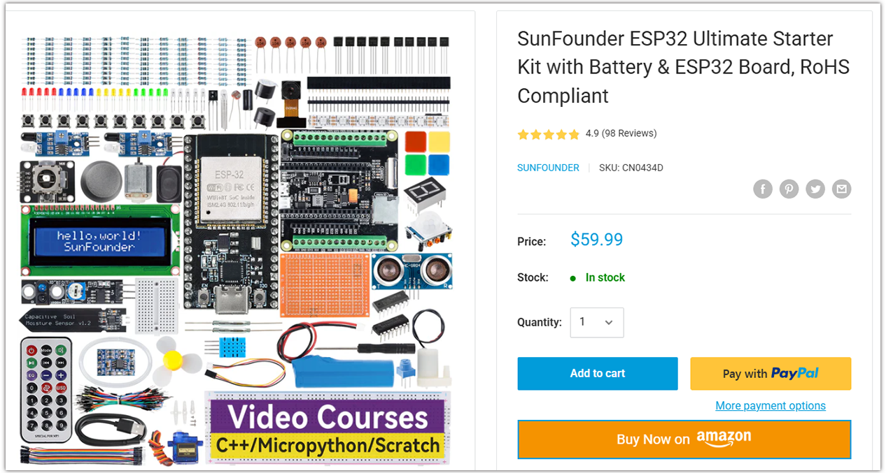
Looking for parts? Check out our all-in-one kits below — packed with components, beginner-friendly guides, and tons of fun.
Name |
Includes ESP32 board |
PURCHASE LINK |
|---|---|---|
ESP32 Ultimate Starter Kit |
ESP32 WROOM 32E + |
|
Universal Maker Sensor Kit |
Course Introduction
This project uses LDRs to detect ambient light changes and control a servo. The original code supports two LDRs, but this experiment uses only one. You can try adding a second LDR for further exploration.
The servo adjusts its angle based on light intensity, simulating responsive movement. A tolerance threshold reduces jitter from small changes. This system is ideal for light-following robots or sun trackers.
Note
If this is your first time working with an ESP32 project, we recommend downloading and reviewing the basic materials first.
Required Components
In this project, we need the following components:
SN |
COMPONENT INTRODUCTION |
QUANTITY |
PURCHASE LINK |
|---|---|---|---|
1 |
ESP-WROOM-32 ESP32 ESP-32S Development Board |
1 |
|
2 |
USB Type-C cable |
1 |
|
3 |
Breadboard |
1 |
|
4 |
Wires |
Several |
|
5 |
Digital Servo Motor |
1 |
|
6 |
Photoresistor Module |
2 |
Wiring

Common Connections:
Digital Servo Motor
Connect to breadboard’s 5V positive power bus.
Connect to breadboard’s negative power bus.
Connect to GPIO16 on the ESP32.
Photoresistor Module Left
A0: Connect to GPIO34 on the ESP32.
GND: Connect to breadboard’s negative power bus.
VCC: Connect to breadboard’s 3.3V red power bus.
Photoresistor Module Right
A0: Connect to GPIO35 on the ESP32.
GND: Connect to breadboard’s negative power bus.
VCC: Connect to breadboard’s 3.3V red power bus.
Writing the Code
Note
You can copy this code into Arduino IDE.
To install the library, use the Arduino Library Manager and search for ESP32Servo and install it.
Don’t forget to select the board(ESP32 Dev module) and the correct port before clicking the Upload button.
// ===== ESP32 version =====
#include <ESP32Servo.h>   // Install "ESP32Servo" via Library Manager

Servo myServo;

// Use ADC1 pins (safe during WiFi/BLE). GPIO34/35 are input-only, perfect for analog.
const int ldrLeft  = 34;   // ADC1_CH6
const int ldrRight = 35;   // ADC1_CH7

const int servoPin = 16;   // Any PWM-capable GPIO (avoid strapping pins)
int pos = 90;              // Initial angle centered (0..180)
int tolerance = 10;        // Deadband to reduce jitter (counts)

// Optional limits & step
const int SERVO_MIN_ANGLE = 0;
const int SERVO_MAX_ANGLE = 180;
const int STEP_PER_LOOP   = 1;   // how many degrees to move per loop

void setup() {
  Serial.begin(115200);
  delay(50);

  // Attach servo with explicit pulse range (common: 500–2500 µs; adjust for your servo)
  myServo.attach(servoPin, 500, 2500);
  myServo.write(pos);

  // ESP32 ADC configuration (12-bit, set per-pin attenuation to read up to ~3.3V)
  analogReadResolution(12);                // 0..4095
  analogSetPinAttenuation(ldrLeft,  ADC_11db);
  analogSetPinAttenuation(ldrRight, ADC_11db);

  Serial.println("ESP32 LDR + Servo tracker ready.");
}

void loop() {
  int leftValue  = analogRead(ldrLeft);    // 0..4095
  int rightValue = analogRead(ldrRight);   // 0..4095
  int difference = leftValue - rightValue; // positive: more light on left

  Serial.print("Left: ");
  Serial.print(leftValue);
  Serial.print(" | Right: ");
  Serial.print(rightValue);
  Serial.print(" | Diff: ");
  Serial.println(difference);

  // Only move if outside deadband
  if (abs(difference) > tolerance) {
    if (difference > 0 && pos < SERVO_MAX_ANGLE) {
      pos += STEP_PER_LOOP;
    } else if (difference < 0 && pos > SERVO_MIN_ANGLE) {
      pos -= STEP_PER_LOOP;
    }
    // Clamp to [0,180]
    if (pos < SERVO_MIN_ANGLE) pos = SERVO_MIN_ANGLE;
    if (pos > SERVO_MAX_ANGLE) pos = SERVO_MAX_ANGLE;

    myServo.write(pos);
  }

  delay(20); // ~50 Hz update rate
}