Nota
¡Hola, bienvenido a la Comunidad de Entusiastas de SunFounder Raspberry Pi & Arduino & ESP32 en Facebook! Sumérgete en Raspberry Pi, Arduino y ESP32 con otros entusiastas.
¿Por qué unirse?
Soporte experto: Resuelve problemas postventa y desafíos técnicos con la ayuda de nuestra comunidad y equipo.
Aprender y compartir: Intercambia consejos y tutoriales para mejorar tus habilidades.
Avances exclusivos: Obtén acceso anticipado a nuevos anuncios de productos y adelantos.
Descuentos especiales: Disfruta de descuentos exclusivos en nuestros productos más recientes.
Promociones y sorteos festivos: Participa en sorteos y promociones especiales de temporada.
👉 ¿Listo para explorar y crear con nosotros? Haz clic en [Aquí] y únete hoy mismo.
4.1.8 Indicador de Batería (MCP3008)
Nota
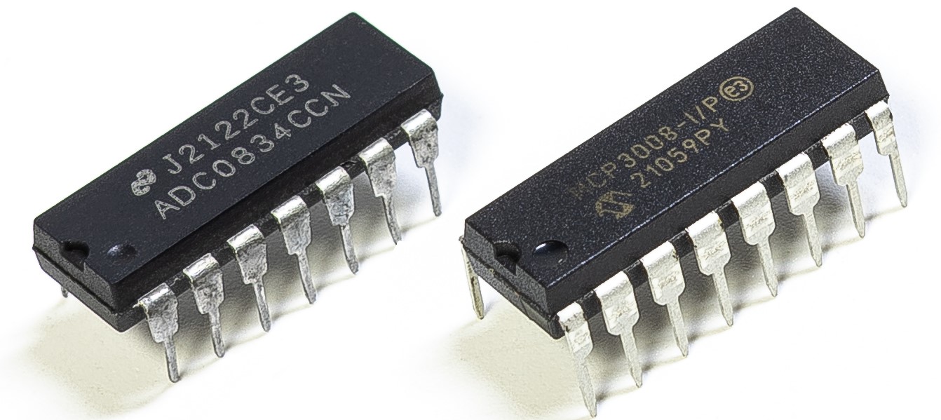
Dependiendo de la versión de tu kit, identifica si tienes ADC0834 o MCP3008 y procede con la sección correspondiente.
Introducción
En este proyecto, haremos un dispositivo indicador de batería que puede mostrar visualmente el nivel de batería en la barra de LED.
Advertencia
No uses componentes de batería que excedan los 3.3V para evitar sobrecargas que puedan dañar el chip o la Raspberry Pi.
Componentes requeridos
En este proyecto, necesitamos los siguientes componentes.
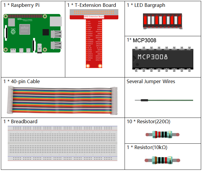
Es definitivamente conveniente comprar un kit completo, aquí tienes el enlace:
Nombre |
ELEMENTOS EN ESTE KIT |
ENLACE |
|---|---|---|
Kit Raphael |
337 |
También puedes comprarlos por separado en los enlaces siguientes.
INTRODUCCIÓN DEL COMPONENTE |
ENLACE DE COMPRA |
|---|---|
- |
|
- |
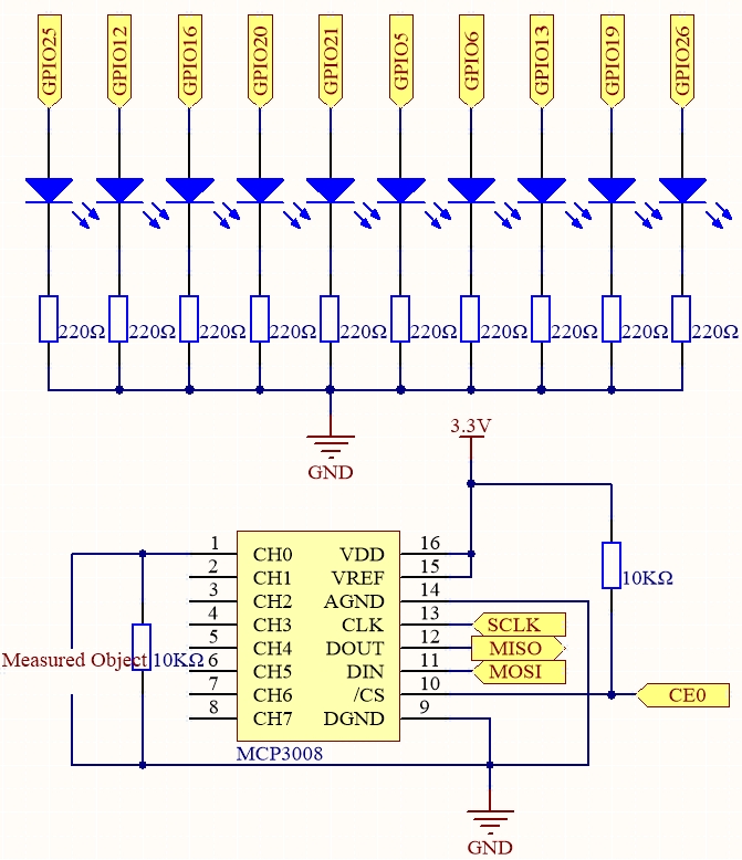
Diagrama esquemático
T-Board Name |
physical |
wiringPi |
BCM |
SPICE0 |
Pin 24 |
10 |
8 |
SPIMOSI |
Pin 19 |
12 |
10 |
SPIMISO |
Pin 21 |
13 |
9 |
SPISCLK |
Pin 23 |
14 |
11 |
GPIO25 |
Pin 22 |
6 |
25 |
GPIO12 |
Pin 32 |
26 |
12 |
GPIO16 |
Pin 36 |
27 |
16 |
GPIO20 |
Pin 38 |
28 |
20 |
GPIO21 |
Pin 40 |
29 |
21 |
GPIO5 |
Pin 29 |
21 |
5 |
GPIO6 |
Pin 31 |
22 |
6 |
GPIO13 |
Pin 33 |
23 |
13 |
GPIO19 |
Pin 35 |
24 |
19 |
GPIO26 |
Pin 37 |
25 |
26 |
Procedimientos experimentales
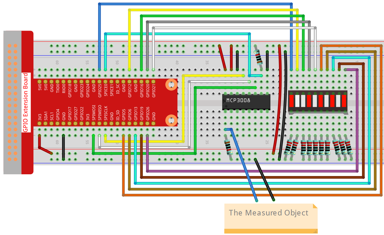
Paso 1: Construye el circuito.
Paso 2: Configura la interfaz SPI e instala la librería spidev (consulta Configuración de SPI para instrucciones detalladas).
Si ya completaste estos pasos, puedes omitirlos.
Paso 3: Ve a la carpeta del código.
cd ~/raphael-kit/python-pi5
Paso 4: Ejecuta el archivo.
sudo python3 4.1.11-2_Battery_indicator_zero.py
Después de ejecutar el programa, conecta un cable desde el pin 3 de MCP3008 y el GND, y luego conéctalos a los dos polos de una batería. Podrás ver los LEDs correspondientes en la barra de LED encenderse para mostrar el nivel de energía (rango de medición: 0-5V).
Advertencia
Si aparece el error RuntimeError: Cannot determine SOC peripheral base address, consulta Si «gpiozero» no funciona.
Código
Nota
Puedes Modificar/Restablecer/Copiar/Ejecutar/Detener el código a continuación.
Pero antes, debes ir a la ruta del código fuente como raphael-kit/python-pi5.
Después de modificar el código, puedes ejecutarlo directamente para ver el efecto.
#!/usr/bin/env python3

import LCD1602
from gpiozero import LED, Buzzer, Button
import spidev
import time
import math

Joy_BtnPin = Button(22)  # GPIO22, Pin15
buzzPin = Buzzer(23)     # GPIO23, Pin16
ledPin = LED(24)         # GPIO24, Pin18

upperTem = 40

spi = spidev.SpiDev()
spi.open(0, 0)
spi.max_speed_hz = 1000000  # 1 MHz

LCD1602.init(0x27, 1)

def read_adc(channel):
    if channel < 0 or channel > 7:
        return -1
    adc = spi.xfer2([1, (8 + channel) << 4, 0])
    value = ((adc[1] & 0x03) << 8) | adc[2]
    return value

def get_joystick_value():
    x_val = read_adc(1)
    y_val = read_adc(2)
    if x_val > 800:
        return 1
    elif x_val < 200:
        return -1
    elif y_val > 800:
        return -10
    elif y_val < 200:
        return 10
    else:
        return 0

def upper_tem_setting():
    global upperTem
    LCD1602.write(0, 0, 'Upper Adjust: ')
    change = int(get_joystick_value())
    upperTem += change
    strUpperTem = str(upperTem)
    LCD1602.write(0, 1, strUpperTem)
    LCD1602.write(len(strUpperTem), 1, '              ')
    time.sleep(0.1)

def temperature():
    analogVal = read_adc(0)
    Vr = 3.3 * analogVal / 1023.0
    if Vr == 0:
        return 0
    Rt = 10000.0 * (3.3 - Vr) / Vr
    temp = 1 / (((math.log(Rt / 10000.0)) / 3950.0) + (1 / (273.15 + 25.0)))
    Cel = temp - 273.15
    return round(Cel, 2)

def monitoring_temp():
    global upperTem
    Cel = temperature()
    LCD1602.write(0, 0, 'Temp: ')
    LCD1602.write(0, 1, 'Upper: ')
    LCD1602.write(6, 0, str(Cel))
    LCD1602.write(7, 1, str(upperTem))
    time.sleep(0.1)
    if Cel >= upperTem:
        buzzPin.on()
        ledPin.on()
    else:
        buzzPin.off()
        ledPin.off()

try:
    lastState = 1
    stage = 0
    while True:
        currentState = Joy_BtnPin.value
        if currentState == 1 and lastState == 0:
            stage = (stage + 1) % 2
            time.sleep(0.1)
            LCD1602.clear()
        lastState = currentState
        if stage == 1:
            upper_tem_setting()
        else:
            monitoring_temp()
except KeyboardInterrupt:
    LCD1602.clear()
    spi.close()
Explicación del código
Este programa de Python se ejecuta en una Raspberry Pi. Usa un convertidor analógico-digital MCP3008 para leer datos de temperatura de un sensor analógico. Un joystick se utiliza para ajustar el umbral de temperatura, y una pantalla LCD1602 muestra la temperatura actual y el umbral. Un zumbador y un LED se activan cuando la temperatura supera el umbral.
Importar librerías necesarias
#!/usr/bin/env python3

import RPi.GPIO as GPIO
import spidev
import time
import math
import LCD1602
Configuración de pines GPIO
JOY_BTN_PIN = 22
BUZZER_PIN = 23
LED_PIN = 24

GPIO.setmode(GPIO.BCM)
GPIO.setup(JOY_BTN_PIN, GPIO.IN, pull_up_down=GPIO.PUD_UP)
GPIO.setup(BUZZER_PIN, GPIO.OUT)
GPIO.setup(LED_PIN, GPIO.OUT)
Inicialización de SPI y LCD
upperTem = 40
spi = spidev.SpiDev()
spi.open(0, 0)
spi.max_speed_hz = 1000000
LCD1602.init(0x27, 1)
Lectura de canal ADC
def read_adc(channel):
    if channel < 0 or channel > 7:
        return -1
    adc = spi.xfer2([1, (8 + channel) << 4, 0])
    value = ((adc[1] & 0x03) << 8) | adc[2]
    return value
Entrada de dirección del joystick
def get_joystick_value():
    x_val = read_adc(1)
    y_val = read_adc(2)
    if x_val > 800:
        return 1
    elif x_val < 200:
        return -1
    elif y_val > 800:
        return -10
    elif y_val < 200:
        return 10
    else:
        return 0
Ajuste del umbral de temperatura
def upper_tem_setting():
    global upperTem
    LCD1602.write(0, 0, 'Upper Adjust: ')
    change = int(get_joystick_value())
    upperTem += change
    strUpperTem = str(upperTem)
    LCD1602.write(0, 1, strUpperTem)
    LCD1602.write(len(strUpperTem), 1, '              ')
    time.sleep(0.1)
Cálculo de temperatura desde el sensor analógico
def temperature():
    analogVal = read_adc(0)
    Vr = 3.3 * analogVal / 1023.0
    if Vr == 0:
        return 0
    Rt = 10000.0 * (3.3 - Vr) / Vr
    tempK = 1.0 / (((math.log(Rt / 10000.0)) / 3950.0) + (1.0 / (273.15 + 25.0)))
    Cel = tempK - 273.15
    return round(Cel, 2)
Modo de monitoreo
def monitoring_temp():
    global upperTem
    Cel = temperature()
    LCD1602.write(0, 0, 'Temp: ')
    LCD1602.write(0, 1, 'Upper: ')
    LCD1602.write(6, 0, str(Cel))
    LCD1602.write(7, 1, str(upperTem))
    time.sleep(0.1)
    if Cel >= upperTem:
        GPIO.output(BUZZER_PIN, GPIO.HIGH)
        GPIO.output(LED_PIN, GPIO.HIGH)
    else:
        GPIO.output(BUZZER_PIN, GPIO.LOW)
        GPIO.output(LED_PIN, GPIO.LOW)
Bucle principal
try:
    lastState = GPIO.input(JOY_BTN_PIN)
    stage = 0
    while True:
        currentState = GPIO.input(JOY_BTN_PIN)
        if currentState == GPIO.HIGH and lastState == GPIO.LOW:
            stage = (stage + 1) % 2
            time.sleep(0.1)
            LCD1602.clear()
        lastState = currentState
        if stage == 1:
            upper_tem_setting()
        else:
            monitoring_temp()
Limpieza al salir
except KeyboardInterrupt:
    pass

finally:
    LCD1602.clear()
    GPIO.cleanup()
    spi.close()