Note
Hello, welcome to the SunFounder Raspberry Pi & Arduino & ESP32 Enthusiasts Community on Facebook! Dive deeper into Raspberry Pi, Arduino, and ESP32 with fellow enthusiasts.
Why Join?
Expert Support: Solve post-sale issues and technical challenges with help from our community and team.
Learn & Share: Exchange tips and tutorials to enhance your skills.
Exclusive Previews: Get early access to new product announcements and sneak peeks.
Special Discounts: Enjoy exclusive discounts on our newest products.
Festive Promotions and Giveaways: Take part in giveaways and holiday promotions.
👉 Ready to explore and create with us? Click [here] and join today!
2.2 - Display the Level
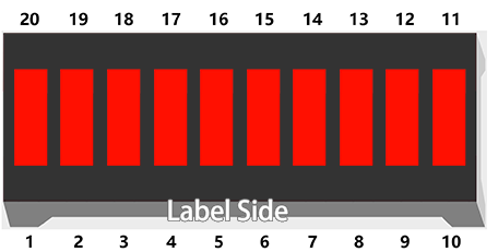
The first project is simply to make the LED blink. In this project let’s use the LED Bar Graph, which is made up of 10 LEDs packaged into a plastic case, generally used to display power or volume levels.
Required Components
In this project, we need the following components.
It’s definitely convenient to buy a whole kit, here’s the link:
Name |
ITEMS IN THIS KIT |
PURCHASE LINK |
|---|---|---|
Kepler Kit |
450+ |
You can also buy them separately from the links below.
SN |
COMPONENT INTRODUCTION |
QUANTITY |
PURCHASE LINK |
|---|---|---|---|
1 |
1 |
||
2 |
Micro USB Cable |
1 |
|
3 |
1 |
||
4 |
Several |
||
5 |
10(220Ω) |
||
6 |
1 |
Schematic
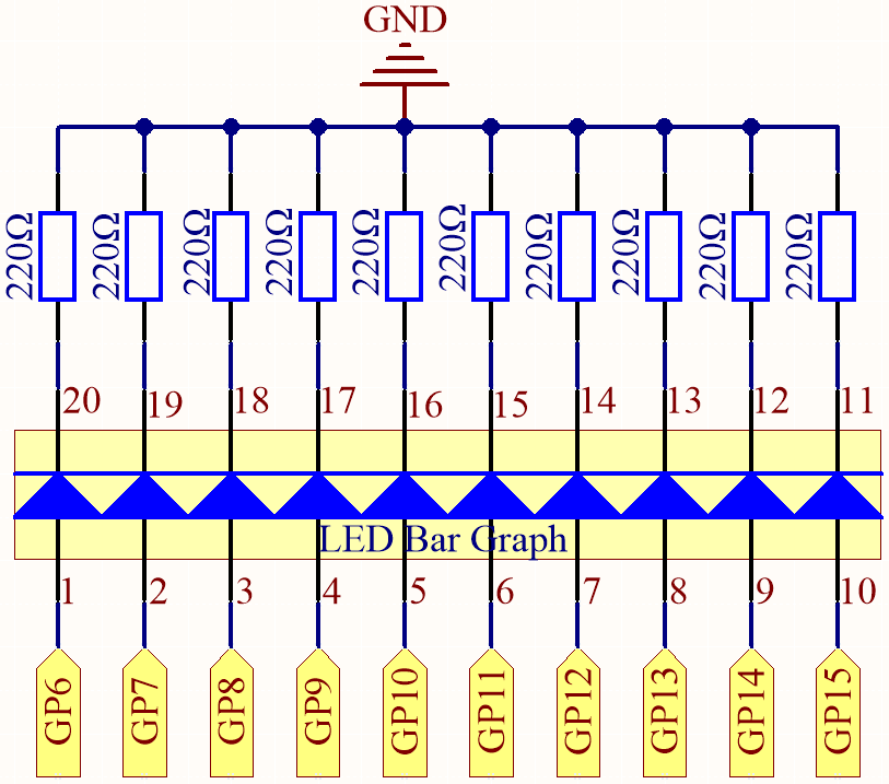
The LED Bar Graph contains 10 LEDs, each of which is individually controllable. Here, the anode of each of the 10 LEDs is connected to GP6~GP15, and the cathode is connected to a 220ohm resistor, and then to GND.
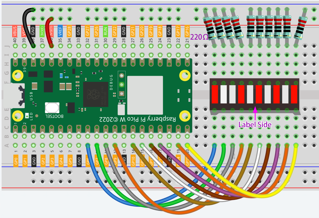
Wiring
Code
Note
You can open the file
2.2_display_the_level.inounder the path ofkepler-kit-main/arduino/2.2_display_the_level.Or copy this code into Arduino IDE.
Don’t forget to select the board(Raspberry Pi Pico) and the correct port before clicking the Upload button.
When the program is running, you will see the LEDs on the LED Bar Graph light up and then turn off in sequence.
How it works?
Each of the ten LEDs on the LED Bar needs to be controlled by a pin, which means that we define these ten pins.
The codes in setup() use the for loop to initialize pins 6~15 to output mode in turn.
for(int i=6;i<=15;i++)
{
    pinMode(i,OUTPUT);
}
The for loop is used in loop() to make the LED flash(turn on 0.5s, then turn off 0.5s) in sequence.
for(int i=6;i<=15;i++)
{
    digitalWrite(i,HIGH);
    delay(500);
    digitalWrite(i,LOW);
    delay(500);
}