Note
Hello, welcome to the SunFounder Raspberry Pi & Arduino & ESP32 Enthusiasts Community on Facebook! Dive deeper into Raspberry Pi, Arduino, and ESP32 with fellow enthusiasts.
Why Join?
Expert Support: Solve post-sale issues and technical challenges with help from our community and team.
Learn & Share: Exchange tips and tutorials to enhance your skills.
Exclusive Previews: Get early access to new product announcements and sneak peeks.
Special Discounts: Enjoy exclusive discounts on our newest products.
Festive Promotions and Giveaways: Take part in giveaways and holiday promotions.
👉 Ready to explore and create with us? Click [here] and join today!
2.7 - Toggle Left and Right
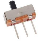
The slide switch is a 3-pin device, with pin 2 (middle) being the common pin. When the switch is toggled to the left, the left two pins are connected together, and when toggled to the right, the right two pins are connected together.
Required Components
In this project, we need the following components.
It’s definitely convenient to buy a whole kit, here’s the link:
Name |
ITEMS IN THIS KIT |
PURCHASE LINK |
|---|---|---|
Kepler Kit |
450+ |
You can also buy them separately from the links below.
SN |
COMPONENT INTRODUCTION |
QUANTITY |
PURCHASE LINK |
|---|---|---|---|
1 |
1 |
||
2 |
Micro USB Cable |
1 |
|
3 |
1 |
||
4 |
Several |
||
5 |
1(10KΩ) |
||
6 |
1(104) |
||
7 |
1 |
Schematic
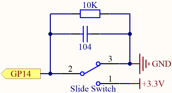
GP14 will get a different level, when you toggle the slide switch to the right or left.
The purpose of the 10K resistor is to keep the GP14 low during toggling (not toggling to the far left and not toggling to the far right).
The 104 ceramic capacitor is used here to eliminate jitter.
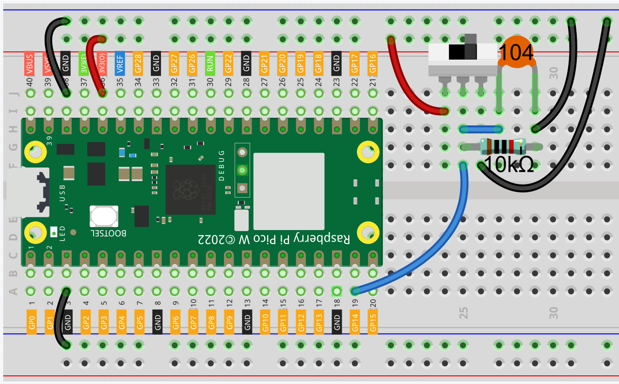
Wiring
Code
Note
You can open the file
2.7_toggle_left_right.inounder the path ofkepler-kit-main/arduino/2.7_toggle_left_right.Or copy this code into Arduino IDE.
Don’t forget to select the board(Raspberry Pi Pico) and the correct port before clicking the Upload button.
When the program is running, the serial monitor will show “ON” or “OFF” when you toggle the switch to the left or right.