Note
Hello, welcome to the SunFounder Raspberry Pi & Arduino & ESP32 Enthusiasts Community on Facebook! Dive deeper into Raspberry Pi, Arduino, and ESP32 with fellow enthusiasts.
Why Join?
Expert Support: Solve post-sale issues and technical challenges with help from our community and team.
Learn & Share: Exchange tips and tutorials to enhance your skills.
Exclusive Previews: Get early access to new product announcements and sneak peeks.
Special Discounts: Enjoy exclusive discounts on our newest products.
Festive Promotions and Giveaways: Take part in giveaways and holiday promotions.
👉 Ready to explore and create with us? Click [here] and join today!
2.4 - Colorful Light
As we know, light can be superimposed. For example, mix blue light and green light give cyan light, red light and green light give yellow light. This is called “The additive method of color mixing”.
Based on this method, we can use the three primary colors to mix the visible light of any color according to different specific gravity. For example, orange can be produced by more red and less green.
In this chapter, we will use RGB LED to explore the mystery of additive color mixing!
RGB LED is equivalent to encapsulating Red LED, Green LED, Blue LED under one lamp cap, and the three LEDs share one cathode pin. Since the electric signal is provided for each anode pin, the light of the corresponding color can be displayed. By changing the electrical signal intensity of each anode, it can be made to produce various colors.
Required Components
In this project, we need the following components.
It’s definitely convenient to buy a whole kit, here’s the link:
Name |
ITEMS IN THIS KIT |
PURCHASE LINK |
|---|---|---|
Kepler Kit |
450+ |
You can also buy them separately from the links below.
SN |
COMPONENT INTRODUCTION |
QUANTITY |
PURCHASE LINK |
|---|---|---|---|
1 |
1 |
||
2 |
Micro USB Cable |
1 |
|
3 |
1 |
||
4 |
Several |
||
5 |
3(1-330Ω, 2-220Ω) |
||
6 |
1 |
Schematic
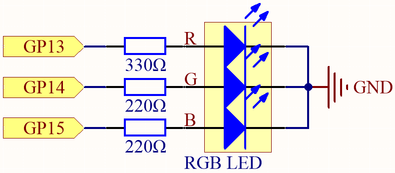
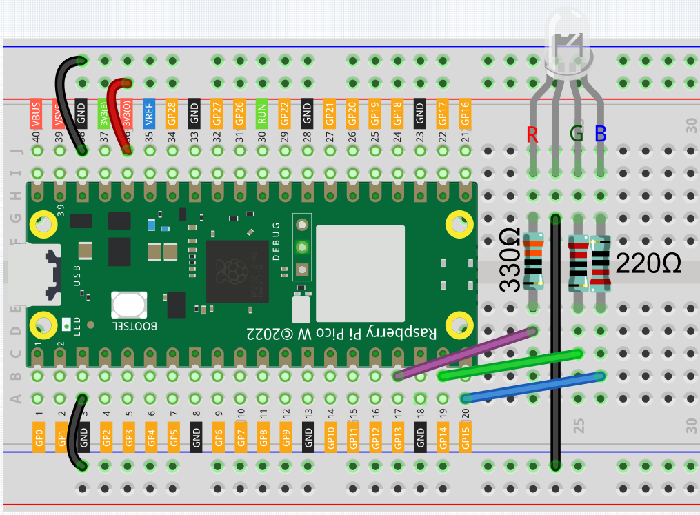
The PWM pins GP13, GP14 and GP15 control the Red, Green and Blue pins of the RGB LED respectively, and connect the common cathode pin to GND. This allows the RGB LED to display a specific color by superimposing light on these pins with different PWM values.
Wiring
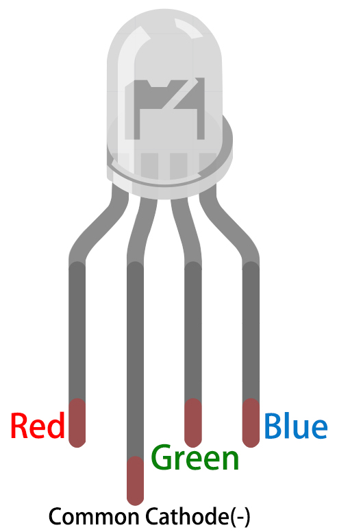
An RGB LED has 4 pins: the longest pin is the common cathode pin, which is usually connected to GND, the left pin next to the longest pin is Red, and the 2 pins on the right are Green and Blue.
Code
Here, we can choose our favorite color in drawing software (such as paint) and display it with RGB LED.
Note
You can open the file
2.4_colorful_light.inounder the path ofkepler-kit-main/arduino/2.4_colorful_light.Or copy this code into Arduino IDE.
Don’t forget to select the board(Raspberry Pi Pico) and the correct port before clicking the Upload button.
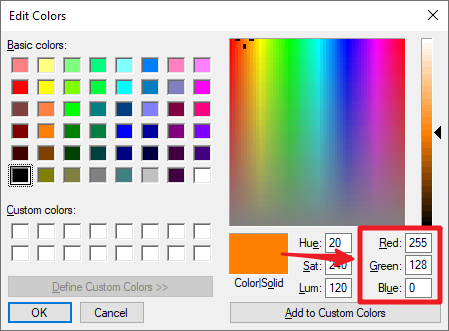
Write the RGB value into color_set(), you will be able to see the RGB light up the colors you want.
How it works?
In this example, the function used to assign values to the three pins of RGB is packaged in an independent subfunction color().
void color (unsigned char red, unsigned char green, unsigned char blue)
{
    analogWrite(redPin, red);
    analogWrite(greenPin, green);
    analogWrite(bluePin, blue);
}
In loop(), RGB value works as an input argument to call the function color() to realize that the RGB can emit different colors.
void loop()
{
    color(255, 0, 0); //  red
    delay(1000);
    color(0,255, 0); //  green
    delay(1000);
    color(0, 0, 255); //  blue
    delay(1000);
}