Note
Hello, welcome to the SunFounder Raspberry Pi & Arduino & ESP32 Enthusiasts Community on Facebook! Dive deeper into Raspberry Pi, Arduino, and ESP32 with fellow enthusiasts.
Why Join?
Expert Support: Solve post-sale issues and technical challenges with help from our community and team.
Learn & Share: Exchange tips and tutorials to enhance your skills.
Exclusive Previews: Get early access to new product announcements and sneak peeks.
Special Discounts: Enjoy exclusive discounts on our newest products.
Festive Promotions and Giveaways: Take part in giveaways and holiday promotions.
👉 Ready to explore and create with us? Click [here] and join today!
5.4 - 8x8 Pixel Graphics
ED matrix is a low-resolution dot-matrix display. it uses an array of light-emitting diodes as pixels for patterned displays.
They are bright enough to be visible in outdoor sunlight, and you can see them on some stores, billboards, signs, and variable message displays (such as those on public transit vehicles).
Used in this kit is an 8x8 dot matrix with 16 pins. Their anodes are connected in rows and their cathodes are connected in columns (at the circuit level), which together control these 64 LEDs.
To light the first LED, you should provide a high level for Row1 and a low level for Col1. To light the second LED, it should provide a high level for Row1, a low level for Col2, and so on. By controlling the current through each pair of rows and columns, each LED can be controlled individually to display characters or pictures.
Required Components
In this project, we need the following components.
It’s definitely convenient to buy a whole kit, here’s the link:
Name |
ITEMS IN THIS KIT |
PURCHASE LINK |
|---|---|---|
Kepler Kit |
450+ |
You can also buy them separately from the links below.
SN |
COMPONENT INTRODUCTION |
QUANTITY |
PURCHASE LINK |
|---|---|---|---|
1 |
1 |
||
2 |
Micro USB Cable |
1 |
|
3 |
1 |
||
4 |
Several |
||
5 |
1 |
||
6 |
2 |
Schematic
![]()
The 8x8 dot matrix is controlled by two 74HC595 chips, one controlling the rows and one controlling the columns, while these two chips share G18~G20, which can greatly save the I/O ports of the Pico W board.
Pico W needs to output a 16-bit binary number at a time, the first 8 bits are given to the 74HC595 which controls the rows, and the last 8 bits are given to the 75HC595 which controls the columns, so that the dot matrix can display a specific pattern.
Q7’: Series output pin, connected to DS of another 74HC595 to connect multiple 74HC595s in series.
Wiring
Build the circuit. Since the wiring is complicated, let’s make it step by step.
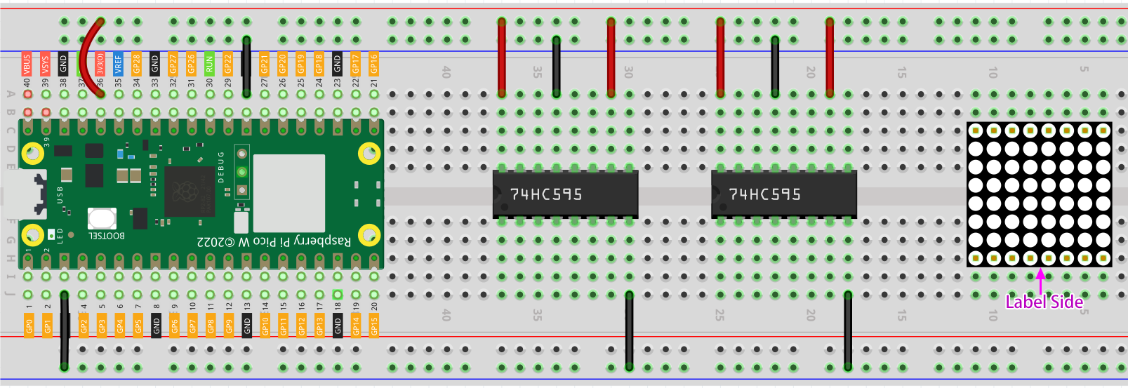
Step 1: First, insert the Pico W, the LED dot matrix and two 74HC595 chips into breadboard. Connect the 3.3V and GND of the Pico W to holes on the two sides of the board, then hook up pin16 and 10 of the two 74HC595 chips to VCC, pin 13 and pin 8 to GND.
Note
In the Fritzing image above, the side with label is at the bottom.
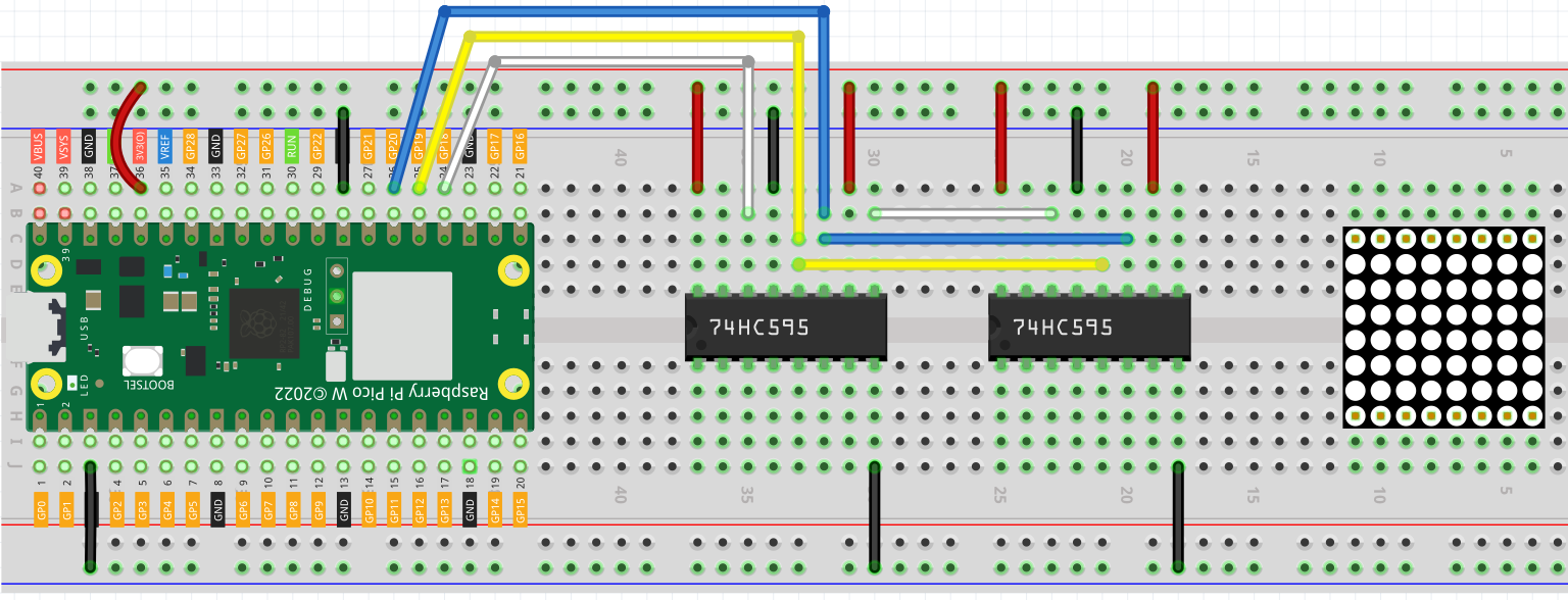
Step 2: Connect pin 11 of the two 74HC595 together, and then to GP20; then pin 12 of the two chips, and to GP19; next, pin 14 of the 74HC595 on the left side to GP18 and pin 9 to pin 14 of the second 74HC595.
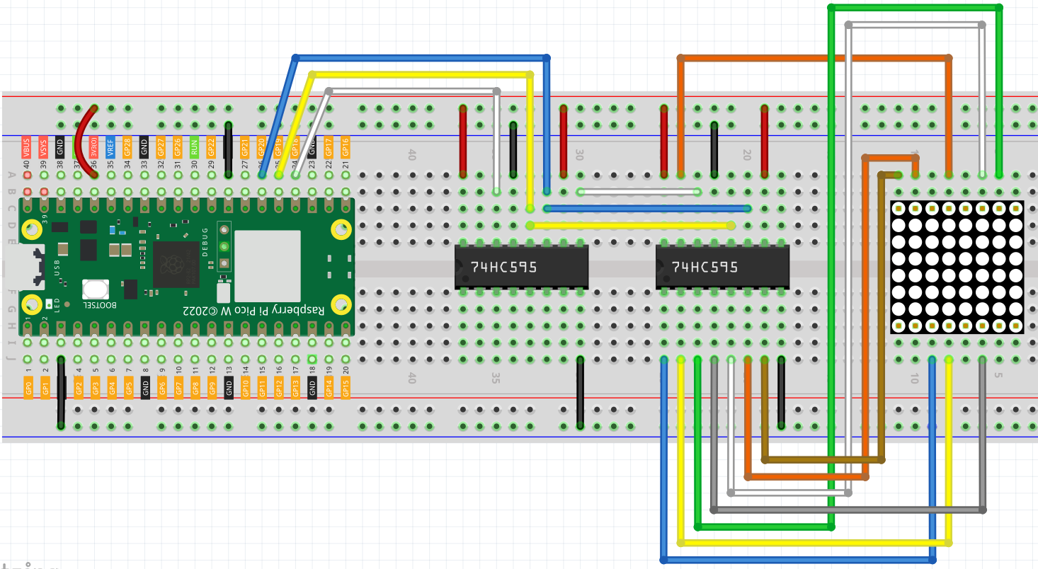
Step 3: The 74HC595 on the right side is to control columns of the LED dot matrix. See the table below for the mapping. Therefore, Q0-Q7 pins of the 74HC595 are mapped with pin 13, 3, 4, 10, 6, 11, 15, and 16 respectively.
74HC595 |
Q0 |
Q1 |
Q2 |
Q3 |
Q4 |
Q5 |
Q6 |
Q7 |
LED Dot Matrix |
13 |
3 |
4 |
10 |
6 |
11 |
15 |
16 |
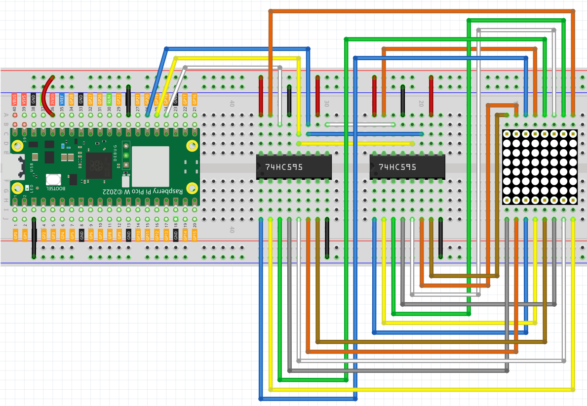
Step 4: Now connect the ROWs of the LED dot matrix. The 74HC595 on the left controls ROW of the LED dot matrix. See the table below for the mapping. We can see, Q0-Q7 of the 74HC595 on the left are mapped with pin 9, 14, 8, 12, 1, 7, 2, and 5 respectively.
74HC595 |
Q0 |
Q1 |
Q2 |
Q3 |
Q4 |
Q5 |
Q6 |
Q7 |
LED Dot Matrix |
9 |
14 |
8 |
12 |
1 |
7 |
2 |
5 |
Code
Note
You can open the file
5.4_8x8_pixel_graphics.inounder the path ofkepler-kit-main/arduino/5.4_8x8_pixel_graphics.Or copy this code into Arduino IDE.
Don’t forget to select the board(Raspberry Pi Pico) and the correct port before clicking the Upload button.
Once the program is running, you will see a x graphic displayed on the 8x8 dot matrix.
How it works?
Here we use two 74HC595s to provide signals for the rows and columns of the dot matrix.
The method of supplying signals is the same as shiftOut() in the previous chapters, except that here we need to write the 16-bit binary number at a time.
The main loop calls shiftOut() twice, writes two 8-bit binary numbers and then outputs them to the bus, so that a pattern can be displayed.
However, since the LEDs in the dot matrix use common poles, controlling multiple rows/multiple columns at the same time will interfere with each other (e.g, if (1,1) and (2,2) are lit at the same time, (1,2) and (2,1) will inevitably be lit together). Therefore, it is necessary to activate one column (or one row) at a time, cycle 8 times, and use the residual image principle to let the human eye merge 8 patterns, so as to let get a pair of patterns containing 8x8 amount of information.
for(int num = 0; num <=8; num++)
{
   digitalWrite(STcp,LOW); //ground ST_CP and hold low for as long as you are transmitting
   shiftOut(DS,SHcp,MSBFIRST,datArray[num]);
   shiftOut(DS,SHcp,MSBFIRST,0x80>>num);
   //return the latch pin high to signal chip that it
   //no longer needs to listen for information
   digitalWrite(STcp,HIGH); //pull the ST_CPST_CP to save the data
}
In this example, the main function nests a for loop, and when i is 1, only the first line is activated (the chip in the control line gets the value 0x80 ) and the image of the first line is written.
When i is 2, the second line is activated (the chip of the control line gets the value 0x40) and the image of the second line is written. And so on, completing 8 outputs.
Incidentally, like the 4-digit 7-segment display, it has to maintain the refresh rate to prevent flickering by the human eye, so the extra sleep() in the main loop should be avoided as much as possible.
Learn More
Try replacing datArray with the following array and see what images appear!
int datArray1[] = {0xFF,0xEF,0xC7,0xAB,0xEF,0xEF,0xEF,0xFF};
int datArray2[] = {0xFF,0xEF,0xEF,0xEF,0xAB,0xC7,0xEF,0xFF};
int datArray3[] = {0xFF,0xEF,0xDF,0x81,0xDF,0xEF,0xFF,0xFF};
int datArray4[] = {0xFF,0xF7,0xFB,0x81,0xFB,0xF7,0xFF,0xFF};
int datArray5[] = {0xFF,0xBB,0xD7,0xEF,0xD7,0xBB,0xFF,0xFF};
int datArray6[] = {0xFF,0xFF,0xF7,0xEB,0xDF,0xBF,0xFF,0xFF};
Or, you can try drawing your own graphics.