Note
Hello, welcome to the SunFounder Raspberry Pi & Arduino & ESP32 Enthusiasts Community on Facebook! Dive deeper into Raspberry Pi, Arduino, and ESP32 with fellow enthusiasts.
Why Join?
Expert Support: Solve post-sale issues and technical challenges with help from our community and team.
Learn & Share: Exchange tips and tutorials to enhance your skills.
Exclusive Previews: Get early access to new product announcements and sneak peeks.
Special Discounts: Enjoy exclusive discounts on our newest products.
Festive Promotions and Giveaways: Take part in giveaways and holiday promotions.
👉 Ready to explore and create with us? Click [here] and join today!
4.1 - Toggle the Joystick
If you play a lot of video games, then you should be very familiar with the Joystick. It is usually used to move the character around, rotate the screen, etc.
The principle behind Joystick’s ability to allow the computer to read our actions is very simple. It can be thought of as consisting of two potentiometers that are perpendicular to each other. These two potentiometers measure the analog value of the joystick vertically and horizontally, resulting in a value (x,y) in a planar right-angle coordinate system.
The joystick of this kit also has a digital input, which is activated when the joystick is pressed.
Required Components
In this project, we need the following components.
It’s definitely convenient to buy a whole kit, here’s the link:
Name |
ITEMS IN THIS KIT |
PURCHASE LINK |
|---|---|---|
Kepler Kit |
450+ |
You can also buy them separately from the links below.
SN |
COMPONENT INTRODUCTION |
QUANTITY |
PURCHASE LINK |
|---|---|---|---|
1 |
1 |
||
2 |
Micro USB Cable |
1 |
|
3 |
1 |
||
4 |
Several |
||
5 |
1(10KΩ) |
||
6 |
1 |
Schematic
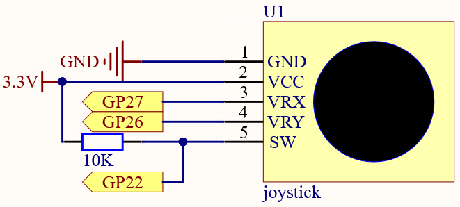
The SW pin is connected to a 10K pull-up resistor, the reason is to be able to get a stable high level on the SW pin (Z axis) when the joystick is not pressed; otherwise the SW is in a suspended state and the output value may vary between 0/1.
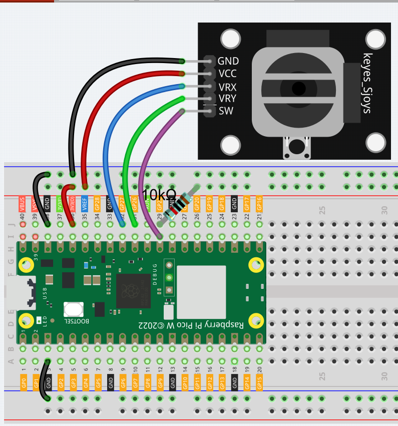
Wiring
Code
Note
You can open the file
4.1_toggle_the_joyostick.inounder the path ofkepler-kit-main/arduino/4.1_toggle_the_joyostick.Or copy this code into Arduino IDE.
Don’t forget to select the board(Raspberry Pi Pico) and the correct port before clicking the Upload button.
After the program runs, the Shell prints out the x,y,z values of joystick.
The x-axis and y-axis values are analog values that vary from 0 to 1023.
The Z-axis is a digital value with a status of 1 or 0.