Note
Hello, welcome to the SunFounder Raspberry Pi & Arduino & ESP32 Enthusiasts Community on Facebook! Dive deeper into Raspberry Pi, Arduino, and ESP32 with fellow enthusiasts.
Why Join?
Expert Support: Solve post-sale issues and technical challenges with help from our community and team.
Learn & Share: Exchange tips and tutorials to enhance your skills.
Exclusive Previews: Get early access to new product announcements and sneak peeks.
Special Discounts: Enjoy exclusive discounts on our newest products.
Festive Promotions and Giveaways: Take part in giveaways and holiday promotions.
👉 Ready to explore and create with us? Click [here] and join today!
2.10 - Detect Human Movement
Passive infrared sensor (PIR sensor) is a common sensor that can measure infrared (IR) light emitted by objects in its field of view. Simply put, it will receive infrared radiation emitted from the body, thereby detecting the movement of people and other animals. More specifically, it tells the main control board that someone has entered your room.
Required Components
In this project, we need the following components.
It’s definitely convenient to buy a whole kit, here’s the link:
Name |
ITEMS IN THIS KIT |
PURCHASE LINK |
|---|---|---|
Kepler Kit |
450+ |
You can also buy them separately from the links below.
SN |
COMPONENT INTRODUCTION |
QUANTITY |
PURCHASE LINK |
|---|---|---|---|
1 |
1 |
||
2 |
Micro USB Cable |
1 |
|
3 |
1 |
||
4 |
Several |
||
5 |
1 |
Schematic
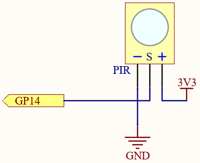
When the PIR module detects someone passing by, GP14 will be high, otherwise it will be low.
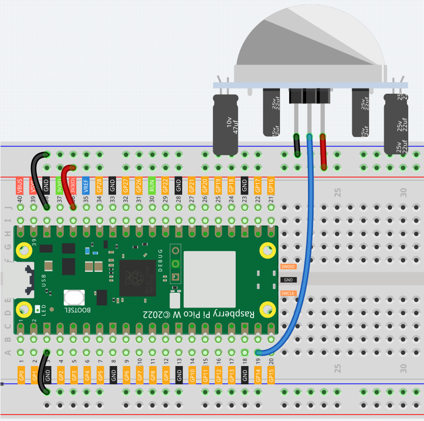
Wiring
Code
Note
You can open the file
2.10_detect_human_movement.inounder the path ofkepler-kit-main/arduino/2.10_detect_human_movement.Or copy this code into Arduino IDE.
Don’t forget to select the board(Raspberry Pi Pico) and the correct port before clicking the Upload button.
After the program runs, if the PIR module detects someone nearby, the Serial Monitor will print out “Somebody here!”
Learn More
PIR is a very sensitive sensor. In order to adapt it to the environment of use, it needs to be adjusted. Let the side with the 2 potentiometers facing you, turn both potentiometers counterclockwise to the end and insert the jumper cap on the pin with L and the middle pin.
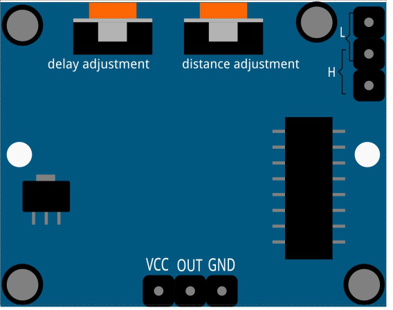
Trigger Mode
Let’s take a look at the pins with jumper cap at the corner. It allows PIR to enter Repeatable trigger mode or Non-repeatable trigger mode
At present, our jumper cap connects the middle Pin and L Pin, which makes the PIR in non-repeatable trigger mode. In this mode, when the PIR detects the movement of the organism, it will send a high-level signal for about 2.8 seconds to the main control board. .. We can see in the printed data that the duration of work will always be around 2800ms.
Next, we modify the position of the lower jumper cap and connect it to the middle Pin and H Pin to make the PIR in repeatable trigger mode. In this mode, when the PIR detects the movement of the organism (note that it is movement, not static in front of the sensor), as long as the organism keeps moving within the detection range, the PIR will continue to send a high-level signal to the main control board. .. We can see in the printed data that the duration of work is an uncertain value.
Delay Adjustment
The potentiometer on the left is used to adjust the interval between two jobs.
At present, we screw it counterclockwise to the end, which makes the PIR need to enter a sleep time of about 5 seconds after finishing sending the high level work. During this time, the PIR will no longer detect the infrared radiation in the target area. .. We can see in the printed data that the dormancy duration is always no less than 5000ms.
If we turn the potentiometer clockwise, the sleep time will also increase. When it is turned clockwise to the end, the sleep time will be as high as 300s.
Distance Adjustment
The centered potentiometer is used to adjust the sensing distance range of the PIR.
Turn the knob of the distance adjustment potentiometer clockwise to increase the sensing distance range, and the maximum sensing distance range is about 0-7 meters. If it rotates counterclockwise, the sensing distance range is reduced, and the minimum sensing distance range is about 0-3 meters.