Note
Hello, welcome to the SunFounder Raspberry Pi & Arduino & ESP32 Enthusiasts Community on Facebook! Dive deeper into Raspberry Pi, Arduino, and ESP32 with fellow enthusiasts.
Why Join?
Expert Support: Solve post-sale issues and technical challenges with help from our community and team.
Learn & Share: Exchange tips and tutorials to enhance your skills.
Exclusive Previews: Get early access to new product announcements and sneak peeks.
Special Discounts: Enjoy exclusive discounts on our newest products.
Festive Promotions and Giveaways: Take part in giveaways and holiday promotions.
👉 Ready to explore and create with us? Click [here] and join today!
2.6 Reed Switch
Introduction
In this project, we will learn how to use a reed switch as a magnetic field sensor to control LEDs. A reed switch is an electrical switch operated by an applied magnetic field, commonly used in security systems, door/window sensors, and position detection. This project demonstrates how to detect the state of a reed switch and provide visual feedback using two LEDs.
What You’ll Need
To complete this project, you will need the following components:
COMPONENT |
PURCHASE LINK |
|---|---|
- |
|
Raspberry Pi |
- |
Circuit Diagram
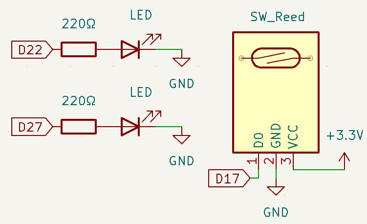
The circuit uses a reed switch connected to a GPIO input pin with a pull-down resistor. Two LEDs are connected to separate GPIO output pins, each with a current-limiting resistor. When a magnet approaches the reed switch, it closes the circuit, triggering the LED indicators to change states.
Wiring Diagram
Follow these steps to build the circuit:
Connect the GND & VCC pin of the reed switch to GND & 3.3V
Connect the D0 Pin of the reed switch to GPIO 17
Connect LED1 cathode to GPIO 22 through a 220Ω resistor
Connect LED1 anode to GND
Connect LED2 cathode to GPIO 27 through a 220Ω resistor
Connect LED2 anode to GND

Running the Example
All example code used in this tutorial is available in the ai-lab-kit directory.
Follow these steps to run the example:
cd ~/ai-lab-kit/python/
sudo python3 2.6_ReedSwitch.py
This Python script creates a magnetic field detection system using a reed switch and two status LEDs. When executed:
The script continuously monitors the state of the reed switch
When a magnet is detected (reed switch closed), LED1 turns off and LED2 turns on
When no magnet is detected (reed switch open), LED1 turns on and LED2 turns off
This creates a clear visual indication of the magnetic field presence
The program can be interrupted gracefully using
Ctrl+C
Code
The following Python code monitors a reed switch and controls two LEDs based on its state:
#!/usr/bin/env python3
from fusion_hat.pin import Pin, Mode, Pull
from time import sleep  # Import sleep for delay

# Initialize reed switch (Button) on GPIO pin 17
reed = Pin(17, mode=Mode.IN, pull=Pull.DOWN)

# Initialize LED1 connected to GPIO pin 22
led1 = Pin(22,mode=Mode.OUT)
# Initialize LED2 connected to GPIO pin 27
led2 = Pin(27,mode=Mode.OUT)

try:
    # Continuously monitor the state of the reed switch and control LEDs accordingly
    while True:
        if reed.value() == 0:  # Check if the reed switch is activated
            led1.off()  # Turn off LED1
            led2.on()   # Turn on LED2
        else:  # If the sensor is not activated
            led1.on()   # Turn on LED1
            led2.off()  # Turn off LED2

except KeyboardInterrupt:
    # Handle a keyboard interrupt (Ctrl+C) for a clean exit from the loop
    pass
Understanding the Code
Library Import
The
Pinclass from thefusion_hatlibrary is used to control GPIO pins, andtime.sleepis imported for potential delay operations.from fusion_hat.pin import Pin, Mode, Pull from time import sleep # Import sleep for delay
Reed Switch Initialization
The reed switch is initialized on GPIO pin 17 as an input with a pull-down resistor to ensure a stable LOW state when the switch is open.
# Initialize reed switch (Button) on GPIO pin 17
reed = Pin(17, mode=Mode.IN, pull=Pull.DOWN)
LED Initialization
Two LEDs are initialized on GPIO pins 22 and 27 as outputs to provide visual feedback.
# Initialize LED1 connected to GPIO pin 22
led1 = Pin(22,mode=Mode.OUT)
# Initialize LED2 connected to GPIO pin 27
led2 = Pin(27,mode=Mode.OUT)
Main Monitoring Loop
The
while Trueloop continuously checks the reed switch state and controls the LEDs accordingly, creating a clear status indication system.while True: if reed.value() == 0: # Check if the reed switch is activated led1.off() # Turn off LED1 led2.on() # Turn on LED2 else: # If the sensor is not activated led1.on() # Turn on LED1 led2.off() # Turn off LED2
Keyboard Interrupt Handling
The
try-exceptblock ensures the program stops gracefully when interrupted.except KeyboardInterrupt: # Handle a keyboard interrupt (Ctrl+C) for a clean exit from the loop pass
Troubleshooting
Reed Switch Not Detecting Magnet
Cause: Magnet polarity issues, insufficient magnetic strength, or wiring problems.
Solution: Try flipping the magnet, use a stronger magnet, or verify all connections.
LEDs Not Lighting
Cause: Incorrect GPIO pin assignments, LED polarity reversed, or insufficient current.
Solution: Check pin assignments, ensure LEDs are connected with correct polarity (anode to GPIO), and verify resistor values.
Unstable Readings
Cause: Electrical noise or floating input when reed switch is open.
Solution: The built-in pull-down resistor should stabilize the input, but ensure proper grounding and check for nearby sources of electromagnetic interference.
Extendable Ideas
Security System
Create a simple door/window security alarm that triggers when a magnet moves away from the reed switch:
# Add a buzzer for audible alarm
from fusion_hat import Buzzer, PWM
buzzer = Buzzer(PWM('P0'))

while True:
    if reed.value() == 1:  # Door opened (magnet moved away)
        buzzer.play('C6', 0.5)  # Sound alarm
        led1.on()  # Red alert LED
    else:
        led2.on()  # Green safe LED
    sleep(0.1)
Position Counter
Count how many times a magnet passes by the reed switch, useful for rotational speed measurement:
counter = 0
last_state = 0

while True:
    current_state = reed.value()
    if last_state == 0 and current_state == 1:  # Detect rising edge
        counter += 1
        print(f"Count: {counter}")
    last_state = current_state
    sleep(0.01)  # Short delay for debouncing
Two-Sensor Detection
Use two reed switches to detect direction of movement:
reed1 = Pin(17, Pin.IN, pull=Pin.PULL_DOWN)
reed2 = Pin(18, Pin.IN, pull=Pin.PULL_DOWN)

# Determine direction based on which sensor triggers first
Conclusion
This project demonstrates how to use a reed switch as a magnetic field sensor to control LED indicators. Reed switches are reliable, simple components widely used in security systems, position sensing, and proximity detection applications. By combining magnetic sensing with visual feedback, you can create intuitive monitoring systems for various applications.