Note
Hello, welcome to the SunFounder Raspberry Pi & Arduino & ESP32 Enthusiasts Community on Facebook! Dive deeper into Raspberry Pi, Arduino, and ESP32 with fellow enthusiasts.
Why Join?
Expert Support: Solve post-sale issues and technical challenges with help from our community and team.
Learn & Share: Exchange tips and tutorials to enhance your skills.
Exclusive Previews: Get early access to new product announcements and sneak peeks.
Special Discounts: Enjoy exclusive discounts on our newest products.
Festive Promotions and Giveaways: Take part in giveaways and holiday promotions.
👉 Ready to explore and create with us? Click [here] and join today!
LED Bar Graph
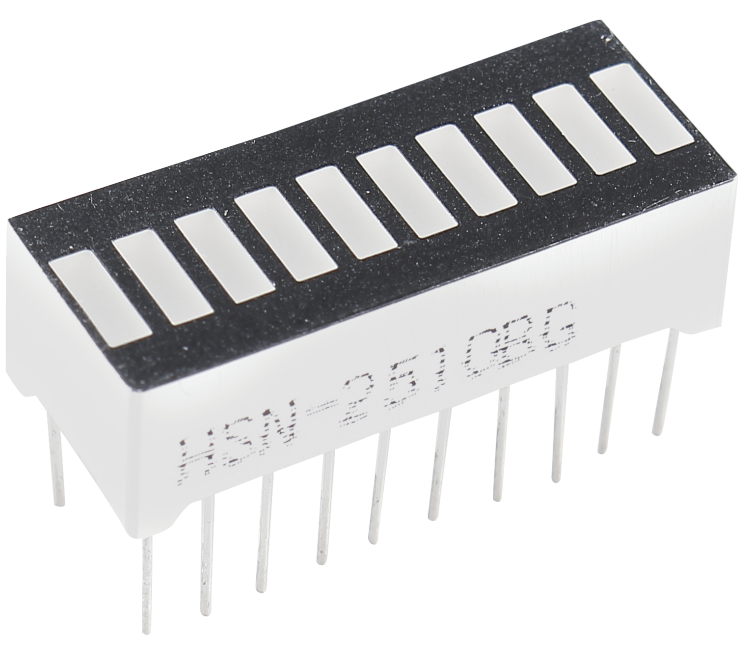
An LED bar graph is an array of LEDs designed to interface with electronic circuits or microcontrollers. Connecting an LED bar graph to a circuit is as straightforward as connecting 10 individual LEDs to 10 output pins. LED bar graphs are commonly used in applications such as battery level indicators, audio equipment, and industrial control panels, among others.
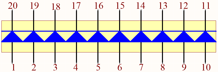
The diagram below illustrates the internal schematic of an LED bar graph. Typically, the side marked with a label represents the anode, while the opposite side corresponds to the cathode.

Example
2.2 Display the Level (For MicroPython User)
2.2 - Display the Level (For Arduino User)