Note
Hello, welcome to the SunFounder Raspberry Pi & Arduino & ESP32 Enthusiasts Community on Facebook! Dive deeper into Raspberry Pi, Arduino, and ESP32 with fellow enthusiasts.
Why Join?
Expert Support: Solve post-sale issues and technical challenges with help from our community and team.
Learn & Share: Exchange tips and tutorials to enhance your skills.
Exclusive Previews: Get early access to new product announcements and sneak peeks.
Special Discounts: Enjoy exclusive discounts on our newest products.
Festive Promotions and Giveaways: Take part in giveaways and holiday promotions.
👉 Ready to explore and create with us? Click [here] and join today!
LED Dot Matrix

LED dot matrices are generally classified into two types: Common Cathode (CC) and Common Anode (CA). While they appear similar externally, their internal configurations differ. The type can be identified through testing. In this kit, a CA dot matrix is used, as indicated by the “788BS” label on the side.
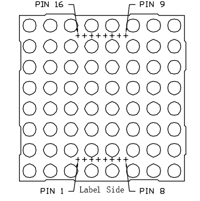
Refer to the figure below for the pin arrangement. The pins are positioned at both ends on the back of the dot matrix. Using the label side as a reference, the pins on this end are numbered 1 to 8, while those on the opposite end are numbered 9 to 16.
The external view:
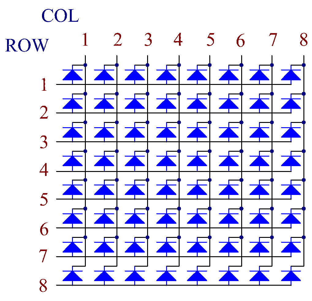
Below the figures show their internal structure. You can see in a CA LED dot matrix, ROW represents the anode of the LED, and COL is cathode; it’s contrary for a CC one. One thing in common: for both types, pin 13, 3, 4, 10, 6, 11, 15, and 16 are all COL, when pin 9, 14, 8, 12, 1, 7, 2, and 5 are all ROW. If you want to turn on the first LED at the top left corner, for a CA LED dot matrix, just set pin 9 as High and pin 13 as Low, and for a CC one, set pin 13 as High and pin 9 as Low. If you want to light up the whole first column, for CA, set pin 13 as Low and ROW 9, 14, 8, 12, 1, 7, 2, and 5 as High, when for CC, set pin 13 as High and ROW 9, 14, 8, 12, 1, 7, 2, and 5 as Low. Consider the following figures for better understanding.
The internal view:
Pin numbering corresponding to the above rows and columns:
COL |
1 |
2 |
3 |
4 |
5 |
6 |
7 |
8 |
Pin No. |
13 |
3 |
4 |
10 |
6 |
11 |
15 |
16 |
ROW |
1 |
2 |
3 |
4 |
5 |
6 |
7 |
8 |
Pin No. |
9 |
14 |
8 |
12 |
1 |
7 |
2 |
5 |
In addition, two 74HC595 chips are used here. One is to control the rows of the LED dot matrix while the other, the columns.
Example
5.4 8x8 Pixel Graphics (For MicroPython User)
7.12 Building a Digital Bubble Level (For MicroPython User)
5.4 Displaying Graphics on an 8x8 LED Matrix (For Arduino User)