Note
Hello, welcome to the SunFounder Raspberry Pi & Arduino & ESP32 Enthusiasts Community on Facebook! Dive deeper into Raspberry Pi, Arduino, and ESP32 with fellow enthusiasts.
Why Join?
Expert Support: Solve post-sale issues and technical challenges with help from our community and team.
Learn & Share: Exchange tips and tutorials to enhance your skills.
Exclusive Previews: Get early access to new product announcements and sneak peeks.
Special Discounts: Enjoy exclusive discounts on our newest products.
Festive Promotions and Giveaways: Take part in giveaways and holiday promotions.
👉 Ready to explore and create with us? Click [here] and join today!
3.1.5 Battery Indicator
Note

Depending on your kit version, please identify whether you have ADC0834 or MCP3008 and proceed with the matching section.
Introduction
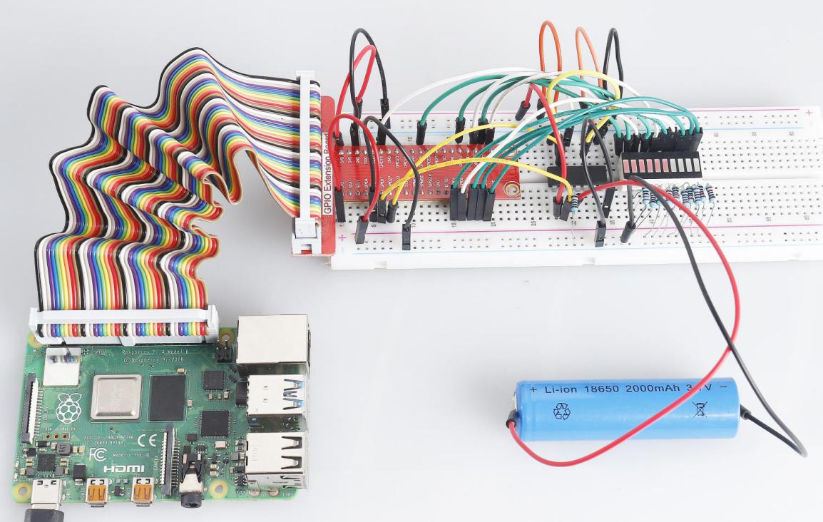
In this project, we will make a battery indicator device that can visually display the battery level on the LED Bargraph.
Warning
Do not use battery components that exceed 3.3V to avoid overloading, which may damage the chip or Raspberry Pi.
Required Components
In this project, we need the following components.
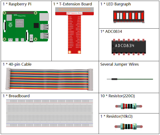
It’s definitely convenient to buy a whole kit, here’s the link:
Name |
ITEMS IN THIS KIT |
LINK |
|---|---|---|
Raphael Kit |
337 |
You can also buy them separately from the links below.
COMPONENT INTRODUCTION |
PURCHASE LINK |
|---|---|
- |
|
- |
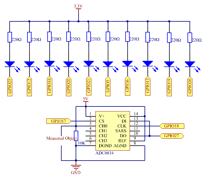
Schematic Diagram
T-Board Name |
physical |
wiringPi |
BCM |
GPIO17 |
Pin 11 |
0 |
17 |
GPIO18 |
Pin 12 |
1 |
18 |
GPIO27 |
Pin 13 |
2 |
27 |
GPIO25 |
Pin 22 |
6 |
25 |
GPIO12 |
Pin 32 |
26 |
12 |
GPIO16 |
Pin 36 |
27 |
16 |
GPIO20 |
Pin 38 |
28 |
20 |
GPIO21 |
Pin 40 |
29 |
21 |
GPIO5 |
Pin 29 |
21 |
5 |
GPIO6 |
Pin 31 |
22 |
6 |
GPIO13 |
Pin 33 |
23 |
13 |
GPIO19 |
Pin 35 |
24 |
19 |
GPIO26 |
Pin 37 |
25 |
26 |
Experimental Procedures
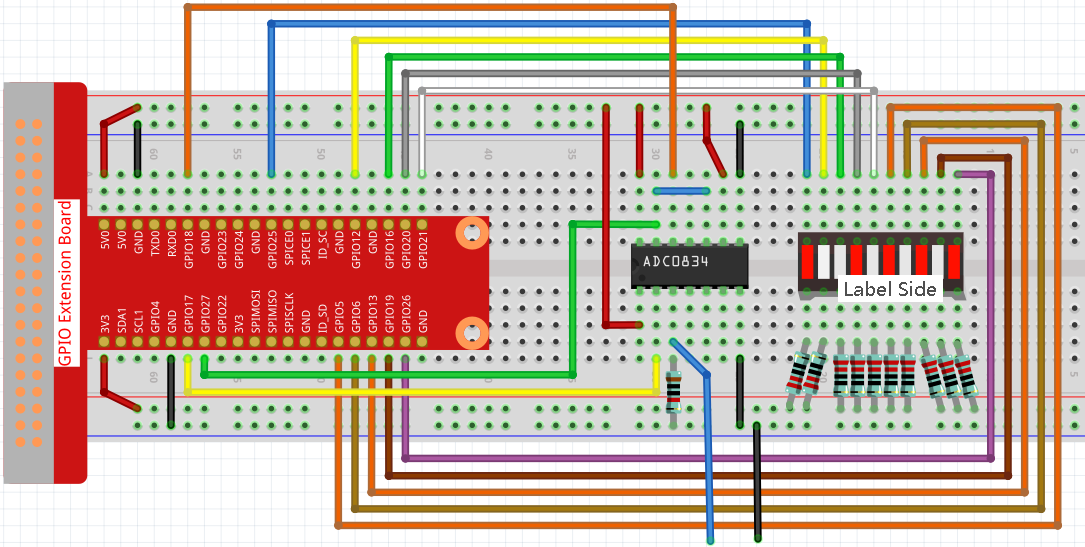
Step 1: Build the circuit.
Step 2: Go to the folder of the code.
cd ~/raphael-kit/c/3.1.5/
Step 3: Compile the code.
gcc 3.1.5_BatteryIndicator.c -lwiringPi
Step 4: Run the executable file.
sudo ./a.out
After the program runs, give the 3rd pin of ADC0834 and the GND a lead-out wire separately and then lead them to the two poles of a battery separately. You can see the corresponding LED on the LED Bargraph is lit up to display the power level (measuring range: 0-5V).
Note
If it does not work after running, or there is an error prompt: "wiringPi.h: No such file or directory", please refer to Install and Check the WiringPi.
Code Explanation
void LedBarGraph(int value){
    for(int i=0;i<10;i++){
        digitalWrite(pins[i],HIGH);
    }
    for(int i=0;i<value;i++){
        digitalWrite(pins[i],LOW);
    }
}
This function works for controlling the turning on or off of the 10 LEDs on the LED Bargraph. We give these 10 LEDs high levels to let they are off at first, then decide how many LEDs are lit up by changing the received analog value.
int main(void)
{
    uchar analogVal;
    if(wiringPiSetup() == -1){ //when initialize wiring failed,print messageto screen
        printf("setup wiringPi failed !");
        return 1;
    }
    pinMode(ADC_CS,  OUTPUT);
    pinMode(ADC_CLK, OUTPUT);
    for(int i=0;i<10;i++){       //make led pins' mode is output
        pinMode(pins[i], OUTPUT);
        digitalWrite(pins[i],HIGH);
    }
    while(1){
        analogVal = get_ADC_Result(0);
        LedBarGraph(analogVal/25);
        delay(100);
    }
    return 0;
}
analogVal produces values (0-255) with varying voltage values (0-5V), ex., if a 3V is detected on a battery, the corresponding value 152 is displayed on the voltmeter.
The 10 LEDs on the LED Bargraph are used to display the analogVal readings. 255/10=25, so every 25 the analog value increases, one more LED turns on, ex., if “analogVal=150 (about 3V), there are 6 LEDs turning on.”
Phenomenon Picture