Note
Hello, welcome to the SunFounder Raspberry Pi & Arduino & ESP32 Enthusiasts Community on Facebook! Dive deeper into Raspberry Pi, Arduino, and ESP32 with fellow enthusiasts.
Why Join?
Expert Support: Solve post-sale issues and technical challenges with help from our community and team.
Learn & Share: Exchange tips and tutorials to enhance your skills.
Exclusive Previews: Get early access to new product announcements and sneak peeks.
Special Discounts: Enjoy exclusive discounts on our newest products.
Festive Promotions and Giveaways: Take part in giveaways and holiday promotions.
👉 Ready to explore and create with us? Click [here] and join today!
Jumper Wires
Wires that connect two terminals are called jumper wires. There are various kinds of jumper wires. Here we focus on those used in breadboard. Among others, they are used to transfer electrical signals from anywhere on the breadboard to the input/output pins of a microcontroller.
Jump wires are fitted by inserting their “end connectors” into the slots provided in the breadboard, beneath whose surface there are a few sets of parallel plates that connect the slots in groups of rows or columns depending on the area. The “end connectors” are inserted into the breadboard, without soldering, in the particular slots that need to be connected in the specific prototype.
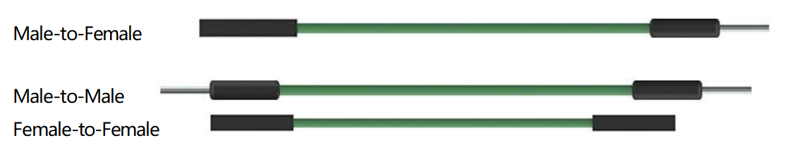
There are three types of jumper wire: Female-to-Female, Male-to-Male, and Male-to-Female. The reason we call it Male-to-Female is because it has the outstanding tip in one end as well as a sunk female end. Male-to-Male means both side are male and Female-to-Female means both ends are female.
More than one type of them may be used in a project. The color of the jump wires is different but it doesn’t mean their function is different accordingly; it’s just designed so to better identify the connection between each circuit.