Note
Hello, welcome to the SunFounder Raspberry Pi & Arduino & ESP32 Enthusiasts Community on Facebook! Dive deeper into Raspberry Pi, Arduino, and ESP32 with fellow enthusiasts.
Why Join?
Expert Support: Solve post-sale issues and technical challenges with help from our community and team.
Learn & Share: Exchange tips and tutorials to enhance your skills.
Exclusive Previews: Get early access to new product announcements and sneak peeks.
Special Discounts: Enjoy exclusive discounts on our newest products.
Festive Promotions and Giveaways: Take part in giveaways and holiday promotions.
👉 Ready to explore and create with us? Click [here] and join today!
LED Bar Graph
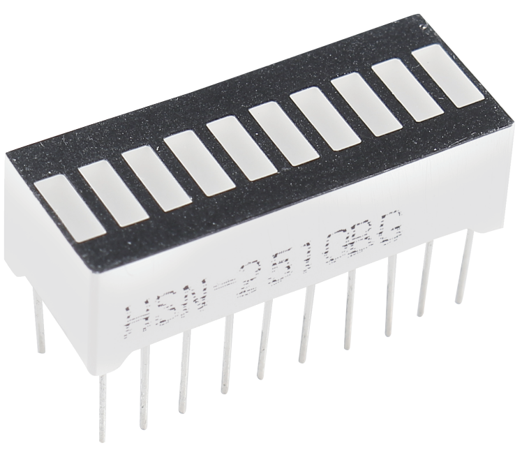
LED Bar Graph is an LED array, which is used to connect with electronic circuit or microcontroller. It’s easy to connect LED bar graph with the circuit like as connecting 10 individual LEDs with 10 output pins. Generally we can use the LED bar graph as a Battery level Indicator, Audio equipments, and Industrial Control panels. There are many other applications of LED bar graphs.
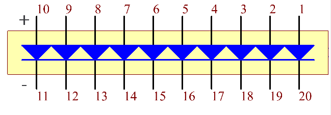
The following is the internal schematic diagram of LED Bar Graph. Generally speaking, the side with the label is the anode and the other side is the cathode.
Example
1.1.3 LED Bar Graph (C Project)
3.1.5 Battery Indicator (C Project)
1.1.3 LED Bar Graph (Python Project)
4.1.11 Battery Indicator (Python Project)
1.12 Water Lamp (Scratch Project)