Lesson 7 Relay
Introduction
As we know relay is a device which is used to provide connection between two or more points or device in response to the input signal applied. In another words relay provide isolation between the controller and the device as we know devices may work on AC as well as on DC. However, they receive signals from microcontroller which works on DC hence we require a relay to bridge the gap. Relay is extremely useful when you need to control a large amount of current or voltage with small electrical signal.
Components
- 1 * Raspberry Pi
- 1 * Breadboard
- 1 * Relay
- 1 * LED
- 1 * Resistor (220Ω)
- 1 * Resistor (1KΩ)
- 1 * NPN Transistor
- 1 * Diode (Rectifier)
- Several jumper wires
- 1 * T-Extension Board
- 1 * 40-Pin GPIO Cable
Principle
Relay
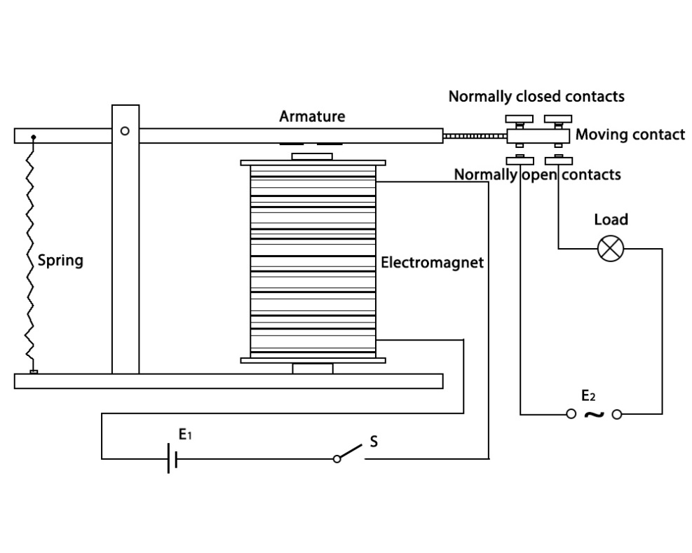
There are 5 parts in every relay:
1. Electromagnet – It consists of an iron core wounded by coil of wires. When electricity is passed through, it becomes magnetic. Therefore, it is calLED electromagnet.
2. Armature – The movable magnetic strip is known as armature. When current flows through them, the coil is it energized thus producing a magnetic field which is used to make or break the normally open (N/O) or normally close (N/C) points. And the armature can be moved with direct current (DC) as well as alternating current (AC).
3. Spring – When no currents flow through the coil on the electromagnet, the spring pulls the armature away so the circuit cannot be completed.
Set of electrical contacts – There are two contact points:
Normally open - connected when the relay is activated, and disconnected when it is inactive.
Normally close – not connected when the relay is activated, and connected when it is inactive.
Molded frame – Relays are covered with plastic for protection.
Working of Relay
The working principle of relay is simple. When power is supplied to the relay, currents start flowing through the control coil; as a result, the electromagnet starts energizing. Then the armature is attracted to the coil, pulling down the moving contact together thus connecting with the normally open contacts. So the circuit with the load is energized. Then breaking the circuit would a similar case, as the moving contact will be pulled up to the normally closed contacts under the force of the spring. In this way, the switching on and off of the relay can control the state of a load circuit.
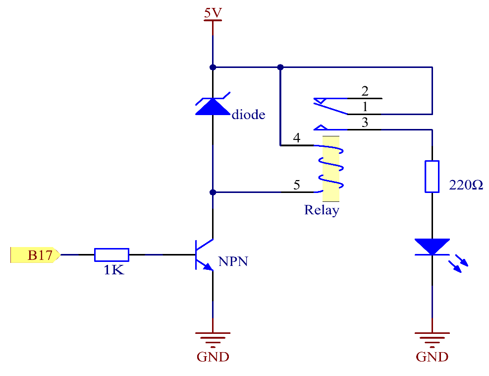
Schematic Diagram:
Experimental Procedures
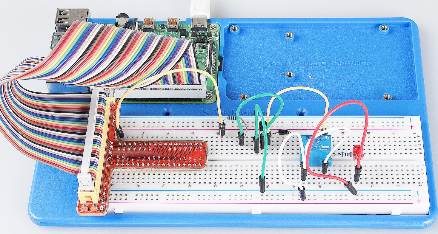
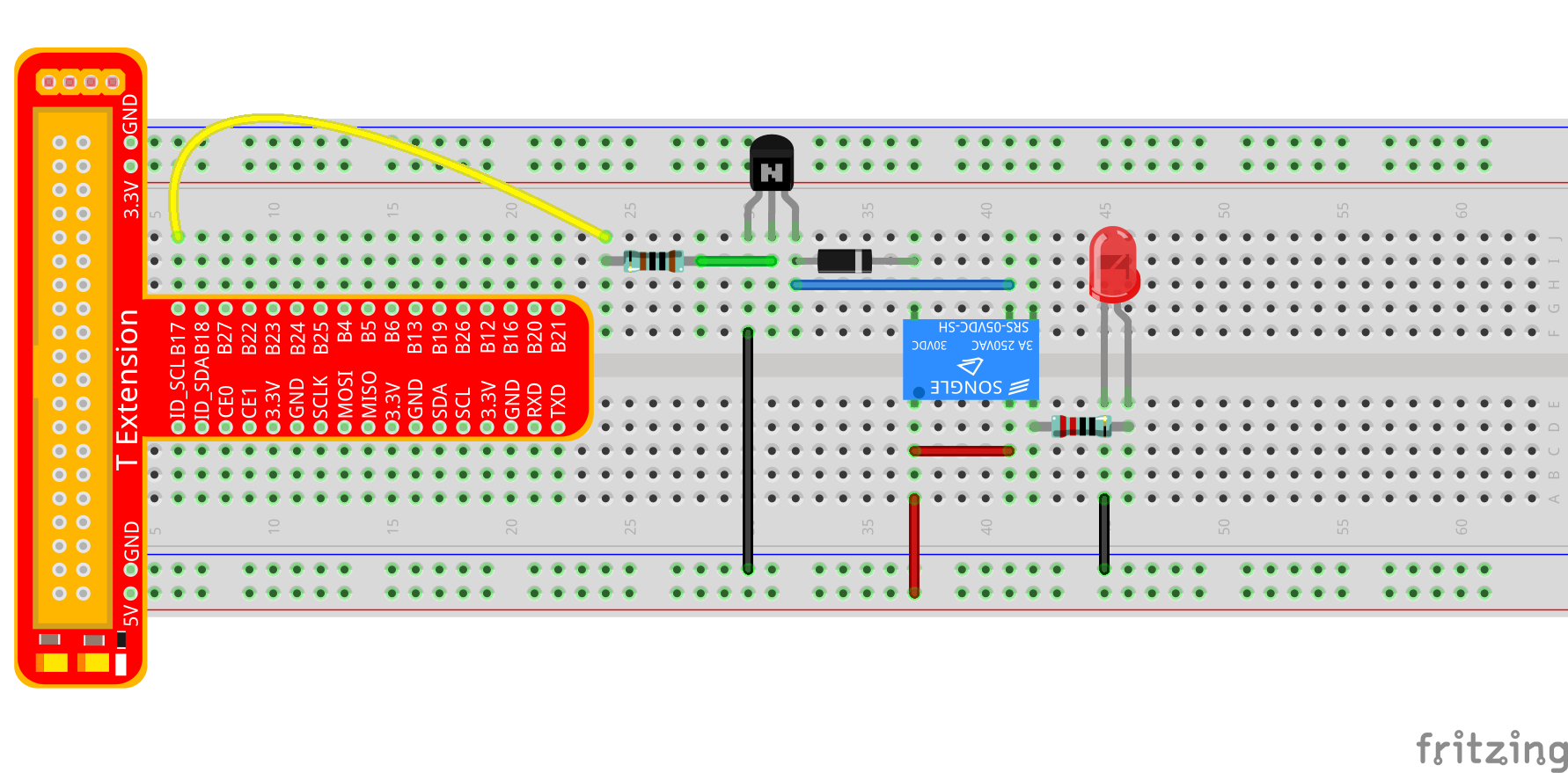
Step 1: Build the circuit.
For C Language Users:
Step 2: Open the code file.
cd /home/pi/SunFounder_Super_Kit_V3.0_for_Raspberry_Pi/C
Step 3: Compile the Code.
make 07_relay
Step 4: Run the executable file above.
sudo ./07_relay
Note
If it does not work after running, or there is an error prompt: “wiringPi.h: No such file or directory”, please refer to C code is not working?.
Code
#include <wiringPi.h>
#include <stdio.h>

#define RelayPin 0

int main(void){
    if(wiringPiSetup() == -1){ //when initialize wiring failed, print messageto screen
        printf("setup wiringPi failed !");
        return 1;
    }

    pinMode(RelayPin, OUTPUT);   //set GPIO0 output

    printf("\n");
    printf("\n");
    printf("========================================\n");
    printf("|                 Relay                |\n");
    printf("|    ------------------------------    |\n");
    printf("| GPIO0 connect to relay's control pin |\n");
    printf("| led connect to relay's NormalOpen pin|\n");
    printf("|  5v connect to relay's com pin       |\n");
    printf("|                                      |\n");
    printf("|      Make relay to contral a led     |\n");
    printf("|                                      |\n");
    printf("|                            SunFounder|\n");
    printf("========================================\n");
    printf("\n");
    printf("\n");

    while(1){
        // Tick
        printf("......Relay Close\n");
        digitalWrite(RelayPin, LOW);
        delay(1000);
        // Tock
        printf("Relay Open......\n");
        digitalWrite(RelayPin, HIGH);
        delay(1000);
    }

    return 0;
}
Code Explanation
digitalWrite(relayPin, LOW); /* Set the I/O port as LOW level (5V), thus
the transistor is not energized and the coil is not powered. There is no
electromagnetic force, so the relay opens.*/

digitalWrite(relayPin, HIGH); /* set the I/O port as HIGH level (0V) to
energize the transistor. The coil of the relay is powered and generate
electromagnetic force, and the relay closes.*/
For Python Users:
Step 2: Open the code file.
cd /home/pi/SunFounder_Super_Kit_V3.0_for_Raspberry_Pi/Python
Step 3: Run.
sudo python3 07_relay.py
Code
import RPi.GPIO as GPIO
import time
from sys import version_info

if version_info.major == 3:
    raw_input = input


# GPIO0 connect to relay's control pin
# led connect to relay's NormalOpen pin
# 5v connect to relay's com pin
# Set #17 as contral pin
relayPin = 17

# Define a function to print message at the beginning
def print_message():
    print ("========================================")
    print ("|                 Relay                |")
    print ("|    ------------------------------    |")
    print ("| GPIO17 connect to relay's control pin |")
    print ("| led connect to relay's NormalOpen pin|")
    print ("|  5v connect to relay's com pin       |")
    print ("|                                      |")
    print ("|      Make relay to contral a led     |")
    print ("|                                      |")
    print ("|                            SunFounder|")
    print ("======================================\n")
    print ("Program is running...")
    print ("Please press Ctrl+C to end the program..")
    #raw_input ("Press Enter to begin\n")

# Define a setup function for some setup
def setup():
    # Set the GPIO modes to BCM Numbering
    GPIO.setmode(GPIO.BCM)
    # Set relayPin's mode to output,
    # and initial level to High(3.3v)
    GPIO.setup(relayPin, GPIO.OUT, initial=GPIO.HIGH)

# Define a main function for main process
def main():
    # Print messages
    print_message()
    while True:
        print ("...Relay close")
        # Tick
        GPIO.output(relayPin, GPIO.LOW)
        time.sleep(1)
        print ("Relay open...")
        # Tock
        GPIO.output(relayPin, GPIO.HIGH)
        time.sleep(1)

# Define a destroy function for clean up everything after
# the script finished
def destroy():
    # Turn off LED
    GPIO.output(relayPin, GPIO.HIGH)
    # Release resource
    GPIO.cleanup()

# If run this script directly, do:
if __name__ == '__main__':
    setup()
    try:
        main()
    # When 'Ctrl+C' is pressed, the child program
    # destroy() will be  executed.
    except KeyboardInterrupt:
        destroy()
Code Explanation
GPIO.output(relayPin, GPIO.LOW)
# Set the pins of the transistor as low level to let the relay open.

time.sleep(1) # wait for 1 second. Change the switching frequency of the
#relay by changing this parameter. Note: Relay is a kind of metal dome
#formed in mechanical structure. So its lifespan will be shortened under
#high-frequency using.

GPIO.output(relayPin, GPIO.HIGH)
# Set the pins of transistor as HIGH level to actuate the relay.

time.sleep(1)
Now, connect a device of high voltage, and the relay will close and the LED will light up; connect one of low voltage, and it will open and the LED will go out. In addition, you can hear a ticktock caused by breaking normally close contact and closing normally open contact.