Lesson 17 ADXL345
Introduction
In this lesson, we will learn how to use the acceleration sensor ADXL345.
Components
- 1 * Raspberry Pi
- 1 * Breadboard
- 1 * ADXL345 module
- 1 * T-Extension Board
- 1 * 40-Pin GPIO Cable
- Jumper wires
Principle
ADXL345
The ADXL345 is a small, thin, low power, 3-axis accelerometer with high resolution (13-bit) measurement at up to ±16 g. Digital output data is formatted as 16-bit two’s complement and is accessible through either an SPI (3- or 4-wire) or I2C digital interface.
The ADXL345 is well suited to measure the static acceleration of gravity in tilt-sensing applications, as well as dynamic acceleration resulting from motion or shock. Its high resolution (4 mg/LSB) enables the inclination change measurement by less than 1.0°. And the excellent sensitivity (3.9mg/LSB @2g) provides a high-precision output of up to ±16g.
In this experiment, I2C digital interface is used.
ADXL345 works like this:
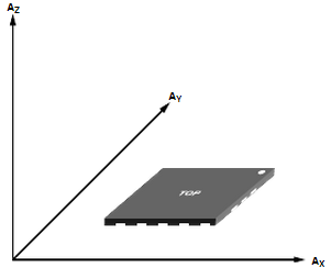
Axes of detection by ADXL345
When you place the module face up, Z_OUT is at the maximum which is +1g; face down, Z_OUT is at the minimum. No matter of face, as long as it’s placed on a level surface, X_OUT increases along the Ax axis direction, so does Y_OUT along the Ay axis. See the picture below. Thus, when you rotate the module, you can see the changes of X_OUT, Y_OUT, and Z_OUT.
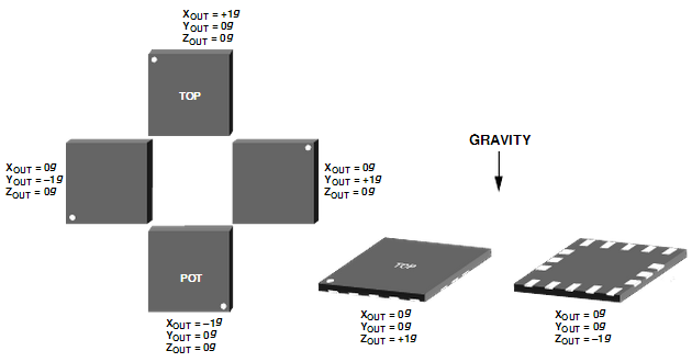
Relationship between output and gravity direction
Pin Function of ADXL345 Module:
Name |
Description |
VS |
Supply Voltage |
CS |
Chip Select; I2C mode is enabled if it’s tie-high to VDD I/O (VDD I/O = 1.8V). |
SDO |
Serial Data Out, alternate I2C address select |
INT1 |
Interrupt 1 Output |
INT2 |
Interrupt 2 Output |
3.3V |
3.3V |
SDA |
Serial Data (I2C), Serial Data In (SPI 4-Wire), Serial Data In/Out (SPI 3-Wire) |
SCL |
Serial Communications Clock |
GND |
GND |
Experimental Procedures
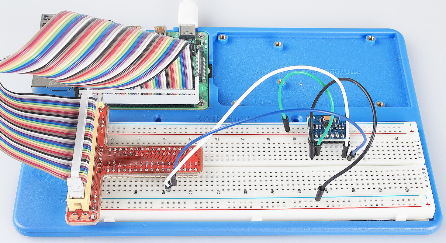
Step 1: Build the circuit.
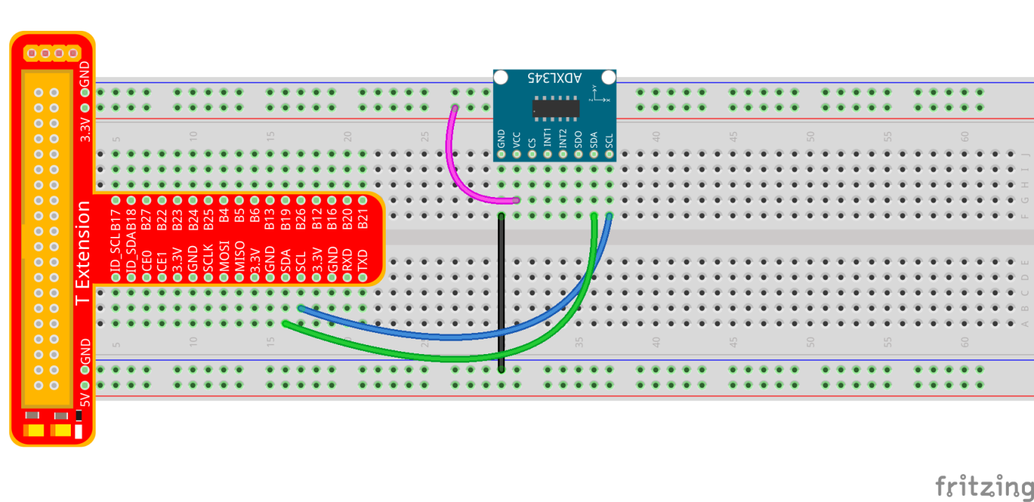
The I2C interface is used in the following program. Before running the program, please make sure the I2C driver module of Raspberry Pi has loaded normally.
For C Language Users:
Step 2: Get into the folder of code.
cd /home/pi/SunFounder_Super_Kit_V3.0_for_Raspberry_Pi/C
Step 3: Compile the Code.
make 17_adxl345
Step 4: Run.
sudo ./17_adxl345
Note
If it does not work after running, or there is an error prompt: “wiringPi.h: No such file or directory”, please refer to C code is not working?.
Code
#include <wiringPiI2C.h>
#include <stdio.h>
#include <stdlib.h>
#include <errno.h>
#include <unistd.h>

#define  DevAddr  0x53  //device address
#define  SENSITIVITY 256.00  //the sensitivity at each axis is 256LSB/g in +-2g,10bit or full resolution

struct acc_dat{
    int x;
    int y;
    int z;
};

void adxl345_init(int fd)
{
    wiringPiI2CWriteReg8(fd, 0x31, 0x0b); //set the range as +-16g & full resolution
    wiringPiI2CWriteReg8(fd, 0x2d, 0x08);
//  wiringPiI2CWriteReg8(fd, 0x2e, 0x00);
    wiringPiI2CWriteReg8(fd, 0x1e, 0x00);
    wiringPiI2CWriteReg8(fd, 0x1f, 0x00);
    wiringPiI2CWriteReg8(fd, 0x20, 0x00);

    wiringPiI2CWriteReg8(fd, 0x21, 0x00);
    wiringPiI2CWriteReg8(fd, 0x22, 0x00);
    wiringPiI2CWriteReg8(fd, 0x23, 0x00);

    wiringPiI2CWriteReg8(fd, 0x24, 0x01);
    wiringPiI2CWriteReg8(fd, 0x25, 0x0f);
    wiringPiI2CWriteReg8(fd, 0x26, 0x2b);
    wiringPiI2CWriteReg8(fd, 0x27, 0x00);

    wiringPiI2CWriteReg8(fd, 0x28, 0x09);
    wiringPiI2CWriteReg8(fd, 0x29, 0xff);
    wiringPiI2CWriteReg8(fd, 0x2a, 0x80);
    wiringPiI2CWriteReg8(fd, 0x2c, 0x0a);
    wiringPiI2CWriteReg8(fd, 0x2f, 0x00);
    wiringPiI2CWriteReg8(fd, 0x38, 0x9f);
}

struct acc_dat adxl345_read_xyz(int fd)
{
    char x0, y0, z0, x1, y1, z1;
    struct acc_dat acc_xyz;

    x0 = 0xff - wiringPiI2CReadReg8(fd, 0x32);
    x1 = 0xff - wiringPiI2CReadReg8(fd, 0x33);
    y0 = 0xff - wiringPiI2CReadReg8(fd, 0x34);
    y1 = 0xff - wiringPiI2CReadReg8(fd, 0x35);
    z0 = 0xff - wiringPiI2CReadReg8(fd, 0x36);
    z1 = 0xff - wiringPiI2CReadReg8(fd, 0x37);

    // printf("  x0 = %d   ",x0);printf("x1 = %d  \n",x1);
    // printf("  y0 = %d   ",y0);printf("y1 = %d  \n",y1);
    // printf("  z0 = %d   ",z0);printf("z1 = %d  \n",z1);

    acc_xyz.x = (int)(x1 << 8) + (int)x0;
    acc_xyz.y = (int)(y1 << 8) + (int)y0;
    acc_xyz.z = (int)(z1 << 8) + (int)z0;

    if(acc_xyz.x > 32767){
        acc_xyz.x -= 65536;
    }
    if(acc_xyz.y > 32767){
        acc_xyz.y -= 65536;
    }
    if(acc_xyz.z >32767){
        acc_xyz.z -= 65536;
    }

    return acc_xyz;
}

int main(void)
{
    int fd;
    struct acc_dat acc_xyz;

    fd = wiringPiI2CSetup(DevAddr);

    if(-1 == fd){
        perror("I2C device setup error");
    }

    adxl345_init(fd);

    while(1){
        acc_xyz = adxl345_read_xyz(fd);
        float x = acc_xyz.x/SENSITIVITY;
        float y = acc_xyz.y/SENSITIVITY;
        float z = acc_xyz.z/SENSITIVITY;
        printf("x: %.2f  y: %.2f  z: %.2f\n", x,y,z);

        sleep(1);
    }

    return 0;
}
Code Explanation
#include <wiringPiI2C.h> // Include functions and method for the IIC protocol

#define DevAddr 0x53 // device address

struct acc_dat
{ // a struct variable to store the value of x,y,and z

    int x;

    int y;

    int z;

};

fd = wiringPiI2CSetup(DevAddr); // This initialises the I2C system with your given device identifier

void adxl345_init(int fd)
{ // Initialize the device by i2c

    wiringPiI2CWriteReg8(fd, 0x31, 0x0b);
    // These write an 8-bit data value into the device register indicated.

    wiringPiI2CWriteReg8(fd, 0x2d, 0x08);
    // Write 0x08 to the address(0x21) of the i2c device

}

struct acc_dat adxl345_read_xyz(int fd)
{
    // a struct function, returning a struct value

    char x0, y0, z0, x1, y1, z1;

    struct acc_dat acc_xyz;

    x0 = 0xff - wiringPiI2CReadReg8(fd, 0x32);
    // These read an 8- or 16-bit value from the device register indicated.

    x1 = 0xff - wiringPiI2CReadReg8(fd, 0x33);
    // Read an 8-bit data from the 0x33 register of the I2C device fd, assign to x1

    y0 = 0xff - wiringPiI2CReadReg8(fd, 0x34);

    y1 = 0xff - wiringPiI2CReadReg8(fd, 0x35);

    z0 = 0xff - wiringPiI2CReadReg8(fd, 0x36);

    z1 = 0xff - wiringPiI2CReadReg8(fd, 0x37);

    printf(" x0 = %d ",x0);printf("x1 = %d \n",x1);

    printf(" y0 = %d ",y0);printf("y1 = %d \n",y1);

    printf(" z0 = %d ",z0);printf("z1 = %d \n",z1);

    acc_xyz.x = (int)(x1 << 8) + (int)x0;
    // Assign values to members of the struct; the value of x consists of x1 (high 8 bits) and x0 (low 8 bits).

    acc_xyz.y = (int)(y1 << 8) + (int)y0;

    acc_xyz.z = (int)(z1 << 8) + (int)z0;

    if(acc_xyz.x > 32767)
    { // Set the value of x as no more than 0x7FFF

        acc_xyz.x -= 65536;

    }

    if(acc_xyz.y > 32767)
    { // Set the value of y as no more than 0x7FFF

        acc_xyz.y -= 65536;

    }

    if(acc_xyz.z > 32767)
    {

        acc_xyz.z -= 65536;

    }

    return acc_xyz; // The function ends, return to the acc_xyz struct

}

acc_xyz = adxl345_read_xyz(fd);
// Call the function to read the data collected by the accelerometer module

printf("x: %05d y: %05d z: %05d\n", acc_xyz.x, acc_xyz.y, acc_xyz.z);
// Print the data collected by the accelerometer; %05d means the printed
// data is a 5-bit one, and the empty bit will be replaced by 0.
For Python Users:
Step 2: Get into the folder of the code.
cd /home/pi/SunFounder_Super_Kit_V3.0_for_Raspberry_Pi/Python
Step 3: Run.
sudo python3 17_adxl345.py
Code
from I2C import I2C
from time import sleep

class ADXL345(I2C):

    ADXL345_ADDRESS          = 0x53
    ADXL345_REG_DATA_FORMAT  = 0x31
    ADXL345_REG_DEVID        = 0x00 # Device ID
    ADXL345_REG_DATAX0       = 0x32 # X-axis data 0 (6 bytes for X/Y/Z)
    ADXL345_REG_POWER_CTL    = 0x2D # Power-saving features control

    ADXL345_DATARATE_0_10_HZ = 0x00
    ADXL345_DATARATE_0_20_HZ = 0x01
    ADXL345_DATARATE_0_39_HZ = 0x02
    ADXL345_DATARATE_0_78_HZ = 0x03
    ADXL345_DATARATE_1_56_HZ = 0x04
    ADXL345_DATARATE_3_13_HZ = 0x05
    ADXL345_DATARATE_6_25HZ  = 0x06
    ADXL345_DATARATE_12_5_HZ = 0x07
    ADXL345_DATARATE_25_HZ   = 0x08
    ADXL345_DATARATE_50_HZ   = 0x09
    ADXL345_DATARATE_100_HZ  = 0x0A # (default)
    ADXL345_DATARATE_200_HZ  = 0x0B
    ADXL345_DATARATE_400_HZ  = 0x0C
    ADXL345_DATARATE_800_HZ  = 0x0D
    ADXL345_DATARATE_1600_HZ = 0x0E
    ADXL345_DATARATE_3200_HZ = 0x0F

    ADXL345_RANGE_2_G        = 0x00 # +/-  2g (default)
    ADXL345_RANGE_4_G        = 0x01 # +/-  4g
    ADXL345_RANGE_8_G        = 0x02 # +/-  8g
    ADXL345_RANGE_16_G       = 0x03 # +/- 16g
    ADXL345_SENSITIVITY      = 256.00 # 256LSB/g in full resolution

    def __init__(self, busnum=1, debug=False):
        self.accel = I2C(self.ADXL345_ADDRESS, busnum, debug)
        if self.accel.readU8(self.ADXL345_REG_DEVID) == 0xE5:
            # Enable the accelerometer
            self.accel.write8(self.ADXL345_REG_POWER_CTL, 0x08)

    def setRange(self, range):
        # Read the data format register to preserve bits.  Update the data
        # rate, make sure that the FULL-RES bit is enabled for range scaling
        format = ((self.accel.readU8(self.ADXL345_REG_DATA_FORMAT) & ~0x0F) |
          range | 0x08)
        # Write the register back to the IC
        self.accel.write8(self.ADXL345_REG_DATA_FORMAT, format)

    def getRange(self):
        return self.accel.readU8(self.ADXL345_REG_DATA_FORMAT) & 0x03

    def setDataRate(self, dataRate):
        # Note: The LOW_POWER bits are currently ignored,
        # we always keep the device in 'normal' mode
        self.accel.write8(self.ADXL345_REG_BW_RATE, dataRate & 0x0F)

    def getDataRate(self):
        return self.accel.readU8(self.ADXL345_REG_BW_RATE) & 0x0F

    # Read the accelerometer
    def read(self):
        raw = self.accel.readList(self.ADXL345_REG_DATAX0, 6)
        #print (raw)
        res = []
        for i in range(0, 6, 2):
            g = raw[i] | (raw[i+1] << 8)
            if g > 32767:
                g -= 65535
            res.append(g/self.ADXL345_SENSITIVITY)
        return res

# Simple example prints accelerometer data once per second:
def main():
    accel = ADXL345()
    accel.setRange(accel.ADXL345_RANGE_16_G)
    while True:
        x, y, z = accel.read()
        print('X: %.2f, Y: %.2f, Z: %.2f'%(x, y, z))
        sleep(1) # Output is fun to watch if this is commented out

def destroy():
    exit()

if __name__ == '__main__':
    try:
        main()
    except KeyboardInterrupt:
        destroy()
Code Explanation
class ADXL345(I2C): # Define a class ADXL345,and the class inheritance is I2C

def __init__(self, busnum=1, debug=False):
# The initialize function of the class, which is run when an instance is created of the class


def setRange(self, range):
# Read the data format register to preserve bits. Update the data rate,
# make sure that the FULL-RES bit is enabled for range scaling:


def getRange(self): # Read an 8-bit data from the device register


def setDataRate(self, dataRate):
# Note: The LOW_POWER bits are currently ignored; we always keep the device in 'normal' mode


def getDataRate(self): # get the rate from the register


def read(self): # Read data from the accelerometer

    raw = self.accel.readList(self.ADXL345_REG_DATAX0, 6)
    # Read 6 values from the register, respectively equal to the high and low bits of the x, y, and z value

    print ( raw)

    res = []

    for i in range(0, 6, 2):

        g = raw[i] | (raw[i+1] << 8)
        # Combine the high 8 bits and low 8 bits and obtain a measurement value g = 65535-g

        if g > 32767:

            g -= 65535

        res.append(g)

    return res

accel = ADXL345() # Create an instance accel of class ADXL345

x, y, z = accel.read() # accel calls itself to measure x, y, and z and store them in a list.
                               # Then assign the values measured to x, y, and z.
Now, rotate the acceleration sensor, and you should see the values printed on the screen change.