Lesson 6 Buzzer
Introduction
In this lesson, we will learn how to drive an active buzzer to beep with a PNP transistor.
Components
- 1 * Raspberry Pi
- 1 * Breadboard
- 1 * Buzzer (Active)
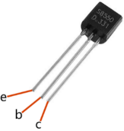
- 1 * PNP transistor (8550)
- 1 * Resistor (1KΩ)
- Jumper wires
- 1 * T-Extension Board
- 1 * 40-Pin GPIO Cable
Principle
Buzzer
As a type of electronic buzzer with integrated structure, buzzers, which are supplied by DC power, are widely used in computers, printers, photocopiers, alarms and other electronic products for voice devices. Buzzers can be categorized as active and passive ones (see the following picture). Turn the pins of two buzzers face up, and the one with a green circuit board is a passive buzzer, while the other enclosed with a black tape is an active one.

The difference between an active buzzer and a passive buzzer is: An active buzzer has a built-in oscillating source, so it will make sounds when electrified. But a passive buzzer does not have such source, so it will not beep if DC signals are used; instead, you need to use square waves whose frequency is between 2K and 5K to drive it. The active buzzer is often more expensive than the passive one because of multiple built-in oscillating circuits.
The following is the electrical symbol of a buzzer. It has two pins with positive and negative poles. With a + in the surface represents the anode and the other is the cathode.
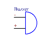
You can check the pins of the buzzer, the longer one is the anode and the shorter one is the cathode. Please don’t mix them up when connecting, otherwise the buzzer will not make sound.
Transistor
The transistor is a semiconductor device that controls current by current. It functions by amplifying weak signal to larger amplitude signal and is also used as a non-contact switch. A transistor is a three-layer structure composed of P-type or N-type semiconductors. They form the three regions internally. The thinner in the middle is the base region; the other two are all N-type or P-type ones – the smaller region with intense majority carriers is the emitter region, when the other one is the collector region. This composition enables the transistor to be an amplifier.
From these three regions, three poles are generated respectively, which are base (b), emitter (e), and collector (c). They form two P-N junctions, namely, the emitter junction and collection junction. The arrow in the circuit symbol indicates the direction of emitter junction. Transistors can be divided into two kinds: the NPN and PNP one. The former is made of two N-type semiconductors and one P-type and that the latter is the opposite. See the figure below.
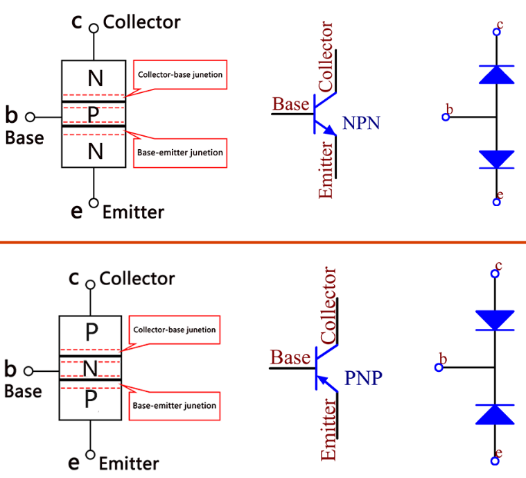
When a High level signal goes through an NPN transistor, it is energized. But a PNP one needs a Low level signal to manage it. Both types of transistor are frequently used for contactless switches, just like in this experiment.
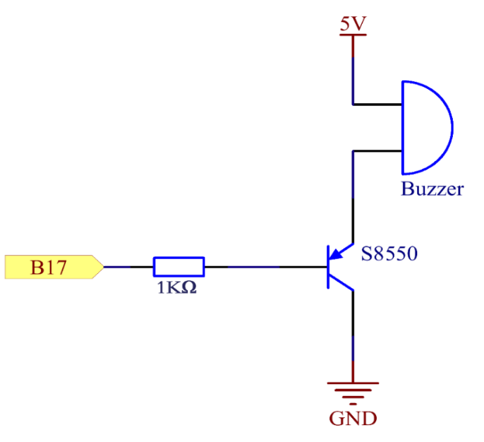
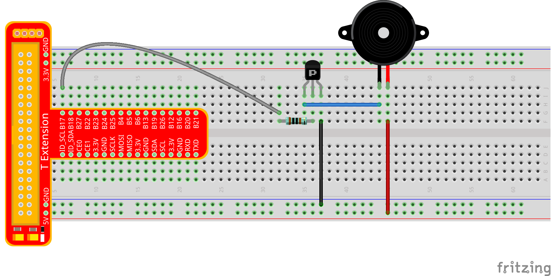
The Schematic Diagram
Principle: In this experiment, an active buzzer, a PNP transistor and a 1k resistor are used between the base of the transistor and GPIO to protect the transistor. When the B17 of Raspberry Pi output is supplied with low level (0V) by programming, the transistor will conduct because of current saturation and the buzzer will make sounds. But when high level is supplied to the IO of Raspberry Pi, the transistor will be cut off and the buzzer will not make sounds
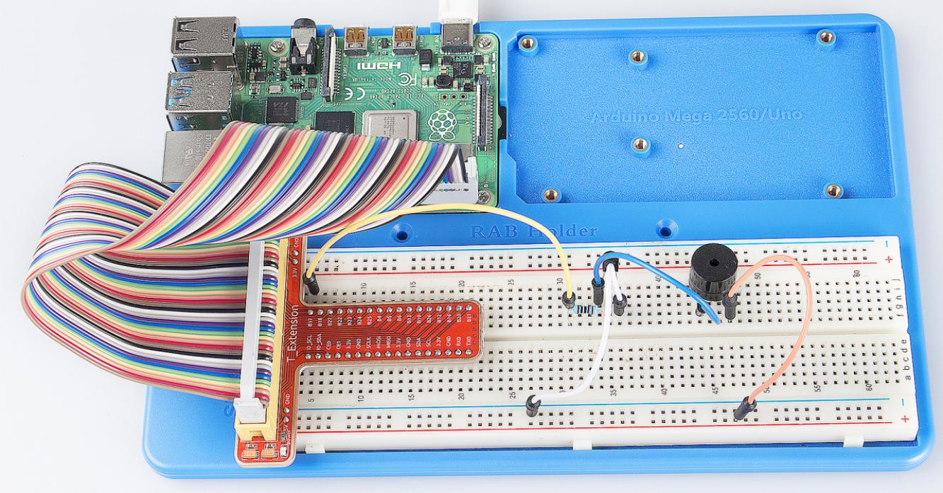
Experimental Procedures
Step 1: Build the circuit (Pay attention to poles of the buzzer: The one with + label is the positive pole and the other is the negative.)
For C Language Users:
Step 2: Open the code file.
cd /home/pi/SunFounder_Super_Kit_V3.0_for_Raspberry_Pi/C
Step 3: Compile the Code.
make 06_beep
Step 4: Run the executable file above.
sudo ./06_beep
Note
If it does not work after running, or there is an error prompt: “wiringPi.h: No such file or directory”, please refer to C code is not working?.
Code
#include <wiringPi.h>
#include <stdio.h>

#define BeepPin 0

int main(void){
    if(wiringPiSetup() == -1){ //when initialize wiring failed, print messageto screen
        printf("setup wiringPi failed !");
        return 1;
    }

    pinMode(BeepPin, OUTPUT);   //set GPIO0 output

    printf("\n");
    printf("\n");
    printf("========================================\n");
    printf("|                 Beep                 |\n");
    printf("|    ------------------------------    |\n");
    printf("|        Buzzer connect to GPIO0       |\n");
    printf("|                                      |\n");
    printf("|            Make Buzzer beep          |\n");
    printf("|                                      |\n");
    printf("|                            SunFounder|\n");
    printf("========================================\n");
    printf("\n");
    printf("\n");

    while(1){
        //beep on
        printf("Buzzer on\n");
        digitalWrite(BeepPin, LOW);
        delay(100);
        printf("Buzzer off\n");
        //beep off
        digitalWrite(BeepPin, HIGH);
        delay(100);
    }

    return 0;
}
Code Explanation
digitalWrite(BeepPin, LOW); /* We use an active buzzer in this
experiment, so it will make sound automatically when connecting to the
direct current. This sketch is to set the I/O port as low level (0V),
thus to manage the transistor and make the buzzer beep.*/

digitalWrite(BeepPin, HIGH); /* To set the I/O port as high level(5V),
thus the transistor is not energized and the buzzer doesn’t beep.*/
For Python Users:
Step 2: Open the code file.
cd /home/pi/SunFounder_Super_Kit_V3.0_for_Raspberry_Pi/Python
Step 3: Run.
sudo python3 06_beep.py
Code
import RPi.GPIO as GPIO
import time
from sys import version_info

if version_info.major == 3:
    raw_input = input


# Set #17 as buzzer pin
BeepPin = 17

def print_message():
    print ("========================================")
    print ("|                 Beep                 |")
    print ("|    ------------------------------    |")
    print ("|        Buzzer connect to GPIO17      |")
    print ("|                                      |")
    print ("|            Make Buzzer beep          |")
    print ("|                                      |")
    print ("|                            SunFounder|")
    print ("======================================\n")
    print ("Program is running...")
    print ("Please press Ctrl+C to end the program...")
    #raw_input ("Press Enter to begin\n")

def setup():
    # Set the GPIO modes to BCM Numbering
    GPIO.setmode(GPIO.BCM)
    # Set LedPin's mode to output,
    # and initial level to High(3.3v)
    GPIO.setup(BeepPin, GPIO.OUT, initial=GPIO.HIGH)

def main():
    print_message()
    while True:
        # Buzzer on (Beep)
        print ("Buzzer On")
        GPIO.output(BeepPin, GPIO.LOW)
        time.sleep(0.1)
        # Buzzer off
        print ("Buzzer Off")
        GPIO.output(BeepPin, GPIO.HIGH)
        time.sleep(0.1)

def destroy():
    # Turn off buzzer
    GPIO.output(BeepPin, GPIO.HIGH)
    # Release resource
    GPIO.cleanup()

# If run this script directly, do:
if __name__ == '__main__':
    setup()
    try:
        main()
    # When 'Ctrl+C' is pressed, the child program
    # destroy() will be  executed.
    except KeyboardInterrupt:
        destroy()
Code Explanation
GPIO.output(BeepPin, GPIO.LOW) # Set the buzzer pin as low level.

time.sleep(0.1) # Wait for 0.1 second. Change the switching frequency by
#changing this parameter. Note: Not the sound frequency. Active Buzzer
#cannot change sound frequency.

GPIO.output(BeepPin, GPIO.HIGH) # close the buzzer

time.sleep(0.1)
Now, you should hear the buzzer make sounds.
Further Exploration
If you have a passive buzzer in hand, you can replace the active buzzer with it. Now you can make a buzzer sound like “do re mi fa so la si do” with just some basic knowledge of programming. Give a try!