Lesson 5 RGB LED
Introduction
Previously we’ve used the PWM technology to control an LED brighten and dim. In this lesson, we will use it to control an RGB LED to flash various kinds of colors.
Components
- 1 * Raspberry Pi
- 1 * Breadboard
- 1 * RGB LED
- 3 * Resistor (220Ω)
- Several jumper wires
- 1 * T-Extension Board
- 1 * 40-Pin GPIO Cable
Principle
In this experiment, we will use a RGB. For details of RGB, please refer to the introduction of RGB LED in Components Introduction.
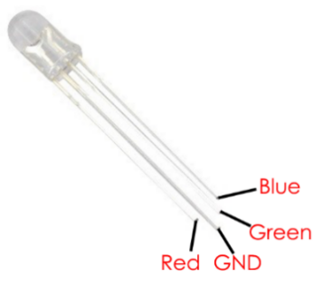
The three primary colors of the RGB LED can be mixed into various colors by brightness. The brightness of LED can be adjusted with PWM. Raspberry Pi has only one channel for hardware PWM output, but it needs three channels to control the RGB LED, which means it is difficult to control the RGB LED with the hardware PWM of Raspberry Pi. Fortunately, the softPwm library simulates PWM (softPwm) by programming. You only need to include the header file softPwm.h (for C language users), and then call the API it provides to easily control the RGB LED by multi-channel PWM output, so as to display all kinds of color.
Experimental Procedures
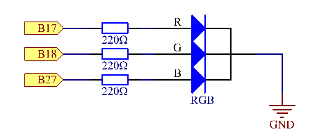
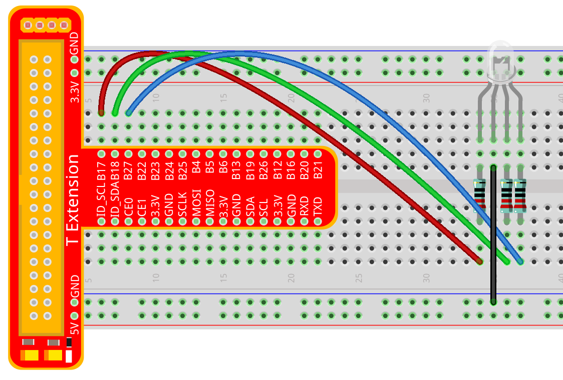
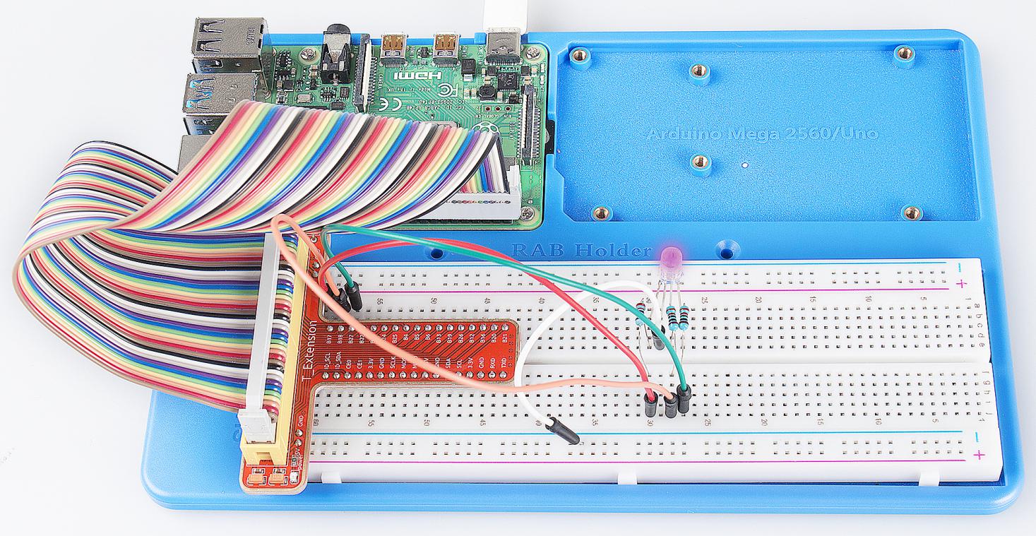
Step 1: Build the circuit.
For C Language Users:
Step 2: Open the code file.
cd /home/pi/SunFounder_Super_Kit_V3.0_for_Raspberry_Pi/C
Step 3: Compile the Code.
make 05_rgb
Step 4: Run the executable file above.
sudo ./05_rgb
Note
If it does not work after running, or there is an error prompt: “wiringPi.h: No such file or directory”, please refer to C code is not working?.
Code
#include <wiringPi.h>
#include <softPwm.h>
#include <stdio.h>

#define uchar unsigned char

#define LedPinRed    0
#define LedPinGreen  1
#define LedPinBlue   2

void ledInit(void){
    softPwmCreate(LedPinRed,  0, 100);
    softPwmCreate(LedPinGreen,0, 100);
    softPwmCreate(LedPinBlue, 0, 100);
}

void ledColorSet(uchar r_val, uchar g_val, uchar b_val){
    softPwmWrite(LedPinRed,   r_val);
    softPwmWrite(LedPinGreen, g_val);
    softPwmWrite(LedPinBlue,  b_val);
}

int main(void){

    if(wiringPiSetup() == -1){ //when initialize wiring failed, printf messageto screen
        printf("setup wiringPi failed !");
        return 1;
    }

    ledInit();

    printf("\n");
    printf("\n");
    printf("========================================\n");
    printf("|              Breath LED              |\n");
    printf("|    ------------------------------    |\n");
    printf("|       Red Pin connect to GPIO0       |\n");
    printf("|      Green Pin connect to GPIO1      |\n");
    printf("|       Blue Pin connect to GPIO2      |\n");
    printf("|                                      |\n");
    printf("|  Make a RGB LED emits various color  |\n");
    printf("|                                      |\n");
    printf("|                            SunFounder|\n");
    printf("========================================\n");
    printf("\n");
    printf("\n");

    while(1){
        printf("Red\n");
        ledColorSet(0xff,0x00,0x00);   //red
        delay(500);
        printf("Green\n");
        ledColorSet(0x00,0xff,0x00);   //green
        delay(500);
        printf("Blue\n");
        ledColorSet(0x00,0x00,0xff);   //blue
        delay(500);

        printf("Yellow\n");
        ledColorSet(0xff,0xff,0x00);   //yellow
        delay(500);
        printf("Purple\n");
        ledColorSet(0xff,0x00,0xff);   //purple
        delay(500);
        printf("Cyan\n");
        ledColorSet(0xc0,0xff,0x3e);   //cyan
        delay(500);
    }

    return 0;
}
Code Explanation
#include <softPwm.h>
// library used for realizing the pwm function of the software.

void ledInit(void)
{ // define function used for initializing I/O port to output for pwm.

    /* LedPinX refers to one pin. 0 is the minimum value and 100 is the
    maximum (as a percentage). The function is to use software to create a
    PWM pin, set its value between 0-100%.*/

    softPwmCreate(LedPinRed, 0, 100);

    softPwmCreate(LedPinGreen,0, 100);

    softPwmCreate(LedPinBlue, 0, 100);

    void ledColorSet(uchar r_val, uchar g_val, uchar b_val)
    { /* This function is to set the colors of the LED. Using RGB, the formal
    parameter r_val represents the luminance of the red one, g_val of the
    green one, b_val of the blue one. The three formal parameters’ different
    values corresponds to various colors. You can modify the 3 formal
    parameters randomly to verify.*/

        softPwmWrite(LedPinRed, r_val);

        softPwmWrite(LedPinGreen, g_val);

        softPwmWrite(LedPinBlue, b_val);

    }

    ledColorSet(0xff,0x00,0x00); /* red calls the function defined before.
    Write oxff into LedPinRed and ox00 into LedPinGreen and LedPinBlue. Only
    the Red LED lights up after running this code. If you want to light up
    LEDs in other colors, just modify the parameters.*/
}
For Python Users:
Step 2: Open the code file.
cd /home/pi/SunFounder_Super_Kit_V3.0_for_Raspberry_Pi/Python
Step 3: Run.
sudo python3 05_rgb.py
Code
import RPi.GPIO as GPIO
import time
from sys import version_info

if version_info.major == 3:
    raw_input = input


# Set up a color table in Hexadecimal
COLOR = [0xFF0000, 0x00FF00, 0x0000FF, 0xFFFF00, 0xFF00FF, 0x00FFFF]
# Set pins' channels with dictionary
pins = {'Red':17, 'Green':18, 'Blue':27}

def print_message():
    print ("========================================")
    print ("|              Breath LED              |")
    print ("|    ------------------------------    |")
    print ("|       Red Pin connect to GPIO17      |")
    print ("|      Green Pin connect to GPIO18     |")
    print ("|       Blue Pin connect to GPIO27     |")
    print ("|                                      |")
    print ("|  Make a RGB LED emits various color  |")
    print ("|                                      |")
    print ("|                            SunFounder|")
    print ("========================================\n")
    print ("Program is running...")
    print ("Please press Ctrl+C to end the program...")
    #raw_input ("Press Enter to begin\n")

def setup():
    global p_R, p_G, p_B
    # Set the GPIO modes to BCM Numbering
    GPIO.setmode(GPIO.BCM)
    # Set all LedPin's mode to output,
    # and initial level to High(3.3v)
    for i in pins:
        GPIO.setup(pins[i], GPIO.OUT, initial=GPIO.HIGH)

    # Set all led as pwm channel,
    #  and frequece to 2KHz
    p_R = GPIO.PWM(pins['Red'], 2000)
    p_G = GPIO.PWM(pins['Green'], 2000)
    p_B = GPIO.PWM(pins['Blue'], 2000)

    # Set all begin with value 0
    p_R.start(0)
    p_G.start(0)
    p_B.start(0)

# Define a MAP function for mapping values.
# Like from 0~255 to 0~100
def MAP(x, in_min, in_max, out_min, out_max):
    return (x - in_min) * (out_max - out_min) / (in_max - in_min) + out_min

# Define a function to set up colors
# input color should be Hexadecimal with
# red value, blue value, green value.
def setColor(color):
    # Devide colors from 'color' veriable
    R_val = (color & 0xFF0000) >> 16
    G_val = (color & 0x00FF00) >> 8
    B_val = (color & 0x0000FF) >> 0

    # Map color value from 0~255 to 0~100
    R_val = MAP(R_val, 0, 255, 0, 100)
    G_val = MAP(G_val, 0, 255, 0, 100)
    B_val = MAP(B_val, 0, 255, 0, 100)

    # Change the colors
    p_R.ChangeDutyCycle(R_val)
    p_G.ChangeDutyCycle(G_val)
    p_B.ChangeDutyCycle(B_val)

    print ("color_msg: R_val = %s,  G_val = %s,     B_val = %s"%(R_val, G_val, B_val))

def main():
    print_message()
    while True:
        for color in COLOR:
            setColor(color)
            time.sleep(0.5)

def destroy():
    # Stop all pwm channel
    p_R.stop()
    p_G.stop()
    p_B.stop()
    # Turn off all LEDs
    #GPIO.output(pins, GPIO.HIGH)
    # Release resource
    GPIO.cleanup()

# If run this script directly, do:
if __name__ == '__main__':
    setup()
    try:
        main()
    # When 'Ctrl+C' is pressed, the child program
    # destroy() will be  executed.
    except KeyboardInterrupt:
        destroy()
Code Explanation
# Set up a color table in Hexadecimal

COLOR = [0xFF0000, 0x00FF00, 0x0000FF, 0xFFFF00, 0xFF00FF, 0x00FFFF]

# Set pins' channels with dictionary

pins = {'Red':17, 'Green':18, 'Blue':27}

p_R = GPIO.PWM(pins['Red'], 2000)
# the same as the last lesson, here we configure the channels and frequencies of the 3 PWM.

p_G = GPIO.PWM(pins['Green'], 2000)

p_B = GPIO.PWM(pins['Blue’], 2000)

p_R.start(0)
# the same as the last lesson, the PWM of the 3 LEDs begin with 0.

p_G.start(0)

p_B.start(0)

# Define a MAP function for mapping values. Like from 0~255 to 0~100

def MAP(x, in_min, in_max, out_min, out_max):

    return (x - in_min) * (out_max - out_min) / (in_max - in_min) + out_min

def setColor(color): # configures the three LEDs’ luminance with the inputted color value .

    R_val = (color & 0xFF0000) >> 16
    # these three lines are used for analyzing the col variables

    G_val = (color & 0x00FF00) >> 8
    # assign the first two values of the hexadecimal to R, the middle two assigned to G

    B_val = (color & 0x0000FF) >> 0
    # assign the last two values to B, please refer to the shift operation of the hexadecimal for details.

    R_val = MAP(R_val, 0, 255, 0, 100)
    # use map function to map the R,G,B value among 0~255 into PWM value among 0-100.

    G_val = MAP(G_val, 0, 255, 0, 100)

    B_val = MAP(B_val, 0, 255, 0, 100)

    p_R.ChangeDutyCycle(R_val)
    # Assign the mapped duty cycle value to the corresponding PWM channel to change the luminance.

    p_G.ChangeDutyCycle(G_val)

    p_B.ChangeDutyCycle(B_val)


for color in COLOR:
# Assign every item in the COLOR list to the color respectively
# and change the color of the RGB LED via the setColor() function.

    setColor(color) # change the color of the RGB LED

    time.sleep(0.5)
    # set delay for 0.5s after each color changing. Modify
    # this parameter will changed the LED’s color changing rate.
Here you should see the RGB LED flash different colors in turn.
You can modify the parameters of the function ledColorSet( ) by yourself, and then and run the code to see the color changes of the RGB LED.