Lesson 12 Rotary Encoder
Introduction
A rotary encoder is an electro-mechanical device that converts the angular position or motion of a shaft or axle to analog or digital code. Rotary encoders are usually placed at the side which is perpendicular to the shaft. They act as sensors for detecting angle, speed, length, position, and acceleration in automation field.
Components
- 1 * Raspberry Pi
- 1 * Breadboard
- 4 * Jumper wires (Male to Male, 2 red and 2 black)
- 1 * Network cable (or USB wireless network adapter)
- 1 * Rotary Encoder module
- 1 * 5-Pin anti-reverse cable
- 1 * T-Extension Board
- 1 * 40-Pin GPIO Cable
Experimental Principle
A rotary encoder is an electronic switch with a set of regular pulses with strictly timing sequence. When used with IC, it can achieve increment, decrement, page turning, and other operations such as mouse scrolling, menu selection, and so on.
There are mainly two types of rotary encoders: absolute and incremental (relative) encoders. Here we use an incremental (relative) encoders.
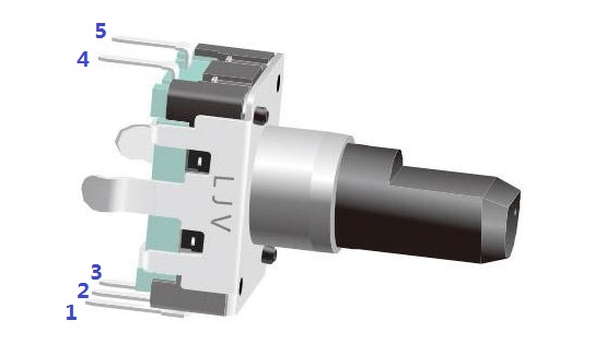
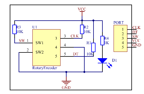
Most rotary encoders have 5 pins with three functions of turning left & right and pressing down. Pin 1 and pin 2 are switch wiring terminals used to press. Pin 4 is generally connected to ground. Pin 3 and pin 5 are first connected to pull-up resistor and connect to VCC. Pin 3 and pin 5 generate two-phase square waves whose phase difference is 90°. Usually the two-phase square waves are called channel A and channel B as shown below:
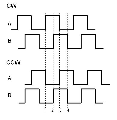
We can see from the figure above: If channel A is in low level, and channel B converts from high level to low, it indicates the Rotary Encoder has spun clockwise (CW). If channel A is in low level, and channel B converts from low level to high, it indicates the Rotary Encoder has spun counter-clockwise (CCW). Thus when channel A is in low level, we can know the direction that Rotary Encoder spun by channel B.
The schematic diagram of the Rotary Encoder is shown as below. We can see that pin 3 on the Rotary Encoder is CLK of the module, while pin 5 is DT. Then we can know the Rotary’s rotating direction by the value of CLK and DT.
It is summarized by using oscilloscope to observe the output waveform of CLK and DT and operating the rotary encoder. You can try yourself.
Experimental Procedures
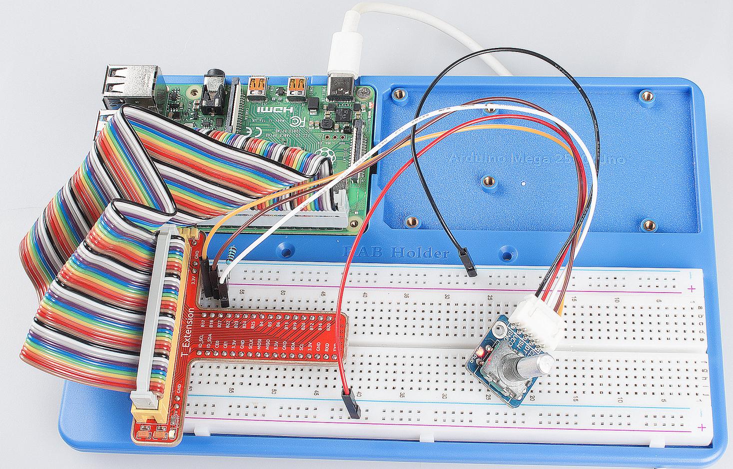
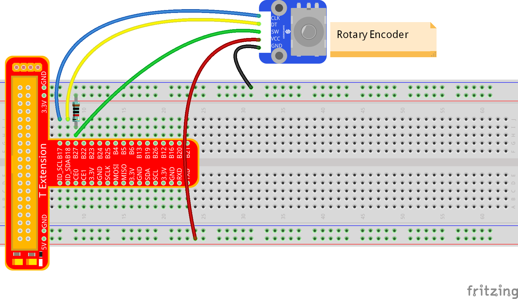
Step 1: Build the circuit.
For C Language Users:
Step 2: Get into the folder of the code.
cd /home/pi/SunFounder_Super_Kit_V3.0_for_Raspberry_Pi/C
Step 3: Compile.
make 12_rotaryEncoder
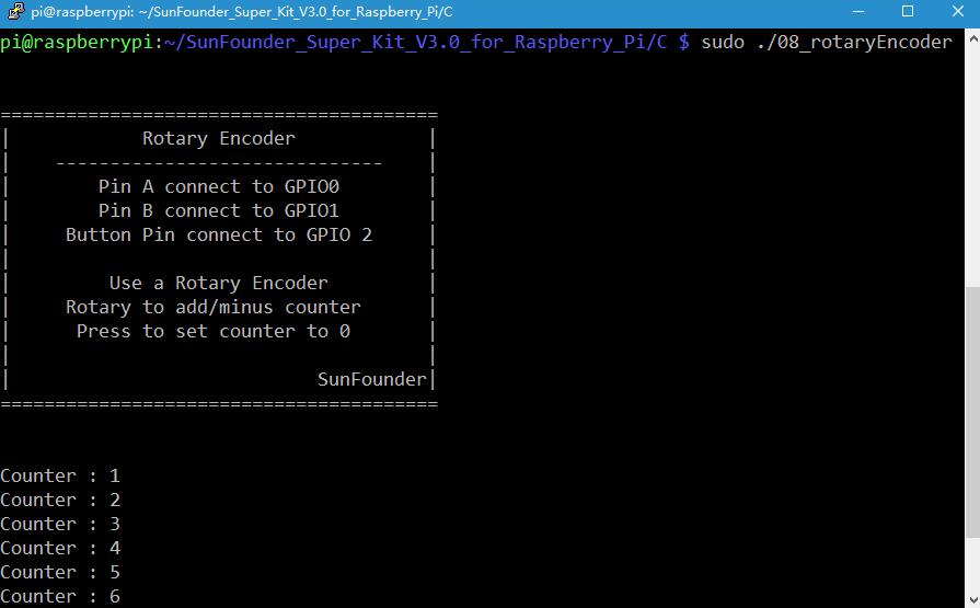
Step 4: Run the executable file above.
sudo ./12_rotaryEncoder
Note
If it does not work after running, or there is an error prompt: “wiringPi.h: No such file or directory”, please refer to C code is not working?.
Code
#include <stdio.h>
#include <string.h>
#include <errno.h>
#include <stdlib.h>
#include <wiringPi.h>

#define  RoAPin    0
#define  RoBPin    1
#define  SWPin     2

static volatile int globalCounter = 0 ;

unsigned char flag;
unsigned char Last_RoB_Status;
unsigned char Current_RoB_Status;

void btnISR(void){
    globalCounter = 0;
}

void rotaryDeal(void){
    Last_RoB_Status = digitalRead(RoBPin);

    while(!digitalRead(RoAPin)){
        Current_RoB_Status = digitalRead(RoBPin);
        flag = 1;
    }

    if(flag == 1){
        flag = 0;
        if((Last_RoB_Status == 0)&&(Current_RoB_Status == 1)){
            globalCounter ++;
        }
        if((Last_RoB_Status == 1)&&(Current_RoB_Status == 0)){
            globalCounter --;
        }
    }
}

int main(void){
    if(wiringPiSetup() < 0){
        printf("Unable to setup wiringPi:%s\n",strerror(errno));
        return 1;
    }

    pinMode(SWPin, INPUT);
    pinMode(RoAPin, INPUT);
    pinMode(RoBPin, INPUT);

    pullUpDnControl(SWPin, PUD_UP);

    if(wiringPiISR(SWPin, INT_EDGE_FALLING, &btnISR) < 0){
        printf("Unable to init ISR:%s\n",strerror(errno));
        return 1;
    }

    printf("\n");
    printf("\n");
    printf("========================================\n");
    printf("|            Rotary Encoder            |\n");
    printf("|    ------------------------------    |\n");
    printf("|        Pin A connect to GPIO0        |\n");
    printf("|        Pin B connect to GPIO1        |\n");
    printf("|     Button Pin connect to GPIO 2     |\n");
    printf("|                                      |\n");
    printf("|         Use a Rotary Encoder         |\n");
    printf("|     Rotary to add/minus counter      |\n");
    printf("|      Press to set counter to 0       |\n");
    printf("|                                      |\n");
    printf("|                            SunFounder|\n");
    printf("========================================\n");
    printf("\n");
    printf("\n");

    int tmp = 0;
    while(1){
        rotaryDeal();
        if (tmp != globalCounter){
            printf("Counter : %d\n",globalCounter);
            tmp = globalCounter;
        }
    }
    return 0;
}
Code Explanation
#define RoAPin 0 // CLK connects to B17, define B17 as 0 in wiring Pi.

#define RoBPin 1 // DT connects to GPIO1, define B18 as 1 in wiring Pi.

#define SWPin 2 // SW connects to GPIO2

void rotaryDeal(void)
/* Pi detects the pulse when spinning the rotary
encoder, and judge the spinning direction, then increase or decrease the
value of globalCounter to record the angular displacement. */
{
    Last_RoB_Status = digitalRead(RoBPin); // Read the value of DT

    while(!digitalRead(RoAPin))  // If CLK is low, run the program below.
    {
        Current_RoB_Status = digitalRead(RoBPin);
        // Read the value of DT, and store it in Current_RoB_Status.
        flag = 1;
    }

    if(flag == 1) // If CLK outputs low level, then flag=1
    {
        flag = 0;
        if((Last_RoB_Status == 0)&&(Current_RoB_Status == 1))
        // If DT value converts from low to high, the globalCounter adds 1.
        {
            globalCounter ++;
        }
        if((Last_RoB_Status == 1)&&(Current_RoB_Status == 0))
        //If DT value converts from high to low
        {
            globalCounter --;  // the globalCounter decreases 1.
        }
    }
}

printf("globalCounter : %d\n",globalCounter); // Print the value of globaCounter.

void btnISR(void): // If the rotary encoder is pressed down, reset the value.
For Python Users:
Step 2: Get into the folder of the code.
cd /home/pi/SunFounder_Super_Kit_V3.0_for_Raspberry_Pi/Python
Step 3: Run.
sudo python3 12_rotaryEncoder.py
Code
import RPi.GPIO as GPIO
import time
from sys import version_info

if version_info.major == 3:
    raw_input = input

# Set up pins
# Rotary A Pin
RoAPin = 17
# Rotary B Pin
RoBPin = 18
# Rotary Switch Pin
RoSPin = 27

def print_message():
    print ("========================================")
    print ("|            Rotary Encoder            |")
    print ("|    ------------------------------    |")
    print ("|        Pin A connect to GPIO17       |")
    print ("|        Pin B connect to GPIO18       |")
    print ("|     Button Pin connect to GPIO27     |")
    print ("|                                      |")
    print ("|         Use a Rotary Encoder         |")
    print ("|     Rotary to add/minus counter      |")
    print ("|      Press to set counter to 0       |")
    print ("|                                      |")
    print ("|                            SunFounder|")
    print ("========================================\n")
    print ("Program is running...")
    print ("Please press Ctrl+C to end the program...")
    #raw_input ("Press Enter to begin\n")

def setup():
    global counter
    global Last_RoB_Status, Current_RoB_Status
    GPIO.setmode(GPIO.BCM)
    GPIO.setup(RoAPin, GPIO.IN)
    GPIO.setup(RoBPin, GPIO.IN)
    GPIO.setup(RoSPin,GPIO.IN, pull_up_down=GPIO.PUD_UP)
    # Set up a falling edge detect to callback clear
    GPIO.add_event_detect(RoSPin, GPIO.FALLING, callback=clear)

    # Set up a counter as a global variable
    counter = 0
    Last_RoB_Status = 0
    Current_RoB_Status = 0

# Define a function to deal with rotary encoder
def rotaryDeal():
    global counter
    global Last_RoB_Status, Current_RoB_Status

    flag = 0
    Last_RoB_Status = GPIO.input(RoBPin)
    # When RoAPin level changes
    while(not GPIO.input(RoAPin)):
        Current_RoB_Status = GPIO.input(RoBPin)
        flag = 1
    if flag == 1:
        # Reset flag
        flag = 0
        if (Last_RoB_Status == 0) and (Current_RoB_Status == 1):
            counter = counter + 1
        if (Last_RoB_Status == 1) and (Current_RoB_Status == 0):
            counter = counter - 1
        print ("counter = %d" % counter)

# Define a callback function on switch, to clean "counter"
def clear(ev=None):
    global counter
    counter = 0

def main():
    print_message()
    while True:
        rotaryDeal()

def destroy():
    # Release resource
    GPIO.cleanup()

# If run this script directly, do:
if __name__ == '__main__':
    setup()
    try:
        main()
    # When 'Ctrl+C' is pressed, the child program
    # destroy() will be  executed.
    except KeyboardInterrupt:
        destroy()
Code Explanation
globalCounter = 0 # Set a global variable to count

flag = 0 # Set a flag for reverse spinning.

Last_RoB_Status = 0 # Set a variable to store the previous state of pinB

Current_RoB_Status = 0 # Set a variable to store the present state of pinB


# Define a function to deal with rotary encoder

def rotaryDeal():

    global counter

    global Last_RoB_Status, Current_RoB_Status

    flag = 0

    Last_RoB_Status = GPIO.input(RoBPin) # Store channel B state

    # When RoAPin level changes

    while(not GPIO.input(RoAPin)): # When channel A is not in low, exit the while loop

        Current_RoB_Status = GPIO.input(RoBPin)

        flag = 1

    if flag == 1: # If flag value is 1, the rotary encoder is CW rotating

        # Reset flag

        flag = 0

        if (Last_RoB_Status == 0) and (Current_RoB_Status == 1):

        counter = counter + 1

        if (Last_RoB_Status == 1) and (Current_RoB_Status == 0):

        counter = counter - 1

        print ("counter = %d" % counter)


    # Define a callback function on switch, to clean "counter"

def clear(ev=None):

    global counter

    counter = 0
Now, gently rotate the encoder to change the value of the variable in the above program, and you will see the value printed on the screen. Rotate the encoder clockwise, the value will increase; or rotate it counterclockwise, the value will decrease.